Security monitoring device

A security monitoring and monitoring host technology, applied in the direction of comprehensive factory control, closed-circuit television system, cleaning methods and appliances, etc., can solve the problems of blurred video, inconvenient cleaning, failure to reach security monitoring, etc., to improve cleaning efficiency, The effect of avoiding interference and avoiding labor costs

Active Publication Date: 2021-05-28
BEIJING TELLHOW INTELLIGENT ENG CO LTD
View PDF6 Cites 0 Cited by
  • Summary
  • Abstract
  • Description
  • Claims
  • Application Information

AI Technical Summary

Problems solved by technology

[0002] As an effective means of security, security monitoring devices have been widely used in scenes such as factories, docks, communities, and prisons. Due to the high pollution of dust in the environment where the above-mentioned security monitoring devices are located, the photography of security monitoring devices in the above-mentioned use environment A large amount of dust and other pollutants often accumulate on the light-transmitting mirror of the camera head, which greatly reduces the light-transmitting performance of the light-transmitting mirror, making the video captured by the camera blurry, and failing to achieve the purpose of security monitoring. In order to achieve the purpose of security monitoring, The light-transmitting lens of the camera head needs to be cleaned. However, the camera head of the existing monitoring device needs to be manually cleaned irregularly. The security monitoring equipment is usually located at a higher position and the monitoring host needs to go back and forth. Rotate to expand the monitoring range, so it is inconvenient to manually clean the light-transmitting lens of the camera, and it is also prone to dangerous accidents

Method used


Image

  • Security monitoring device
  • Security monitoring device
  • Security monitoring device

Examples


Embodiment Construction

[0034] The following is further described in detail through specific implementation methods:

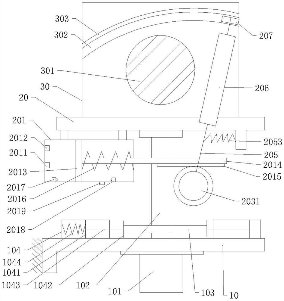
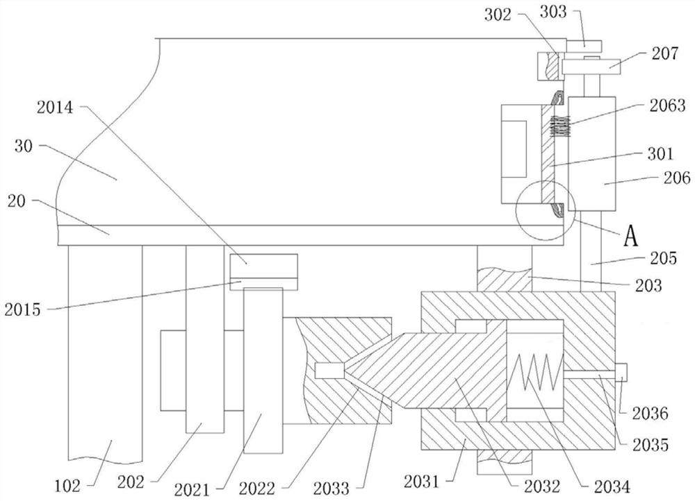
[0035] The reference signs in the accompanying drawings of the specification include: frame 10, motor 101, transmission shaft 102, cam 103, air cylinder 104, first piston 1041, push plate 1042, first push rod 1043, first compression spring 1044, moving plate 20. Gas tank 201, first air inlet 2011, first air outlet 2012, second piston 2013, second push rod 2014, first rack 2015, second compression spring 2016, first contact switch 2017, second Two contact switches 2018, the second air outlet 2019, the first bearing seat 202, the first gear 2021, the first taper hole 2022, the second bearing seat 203, the rotating sleeve 2031, the rotating rod 2032, the first tapered surface 2033, the first Extension spring 2034, second air inlet 2035, second air inlet check valve 2036, limit plate 2037, second tapered hole 2041, tapered block 2042, limit rod 2043, third extension spring 2044, swing ro...


PUM


Abstract

The invention relates to the technical field of monitoring, in particular to a security monitoring device which comprises a rack, a movable plate and a monitoring host, a motor is fixedly connected to the rack, the movable plate is fixedly connected with an output shaft of the motor, the monitoring host is located on the movable plate and fixedly connected with the movable plate, and a light transmitting mirror is arranged on a front panel of the monitoring host. A cam and an air barrel matched with the cam are fixedly connected to a transmission shaft, an air storage box is arranged on the movable plate, a piston is arranged in the air storage box, a push rod provided with a rack is fixedly connected to the piston, a gear meshed with the rack and a rotating sleeve capable of being in contact with or disconnected from the gear are arranged on the movable plate, and a cleaning mechanism for cleaning the light transmitting mirror is arranged on the rotating sleeve. According to the scheme, a series of devices which correlate and interact are arranged to convert the rotary motion of the monitoring host into rhythmic automatic cleaning of the light transmitting mirror, so that the light transmission of the light transmitting mirror is effectively improved to improve the monitoring quality of the monitoring host, and meanwhile, the danger and high labor cost generated during manual cleaning are avoided.

Description

technical field [0001] The invention relates to the technical field of monitoring, in particular to a security monitoring device. Background technique [0002] As an effective means of security, security monitoring devices have been widely used in scenes such as factories, docks, communities, and prisons. Due to the high pollution of dust in the environment where the above-mentioned security monitoring devices are located, the photography of security monitoring devices in the above-mentioned use environment A large amount of dust and other pollutants often accumulate on the light-transmitting mirror of the camera head, which greatly reduces the light-transmitting performance of the light-transmitting mirror, making the video captured by the camera blurry, and failing to achieve the purpose of security monitoring. In order to achieve the purpose of security monitoring, The light-transmitting lens of the camera head needs to be cleaned. However, the camera head of the existing...

Claims


Application Information

Patent Timeline
Patent Type & Authority Applications(China)
IPC IPC(8): B08B1/00B08B1/04B08B5/02B08B13/00H04N7/18
CPCB08B5/02B08B1/002B08B1/006B08B1/04B08B13/00H04N7/18Y02P90/02
Inventor 陈军
Owner BEIJING TELLHOW INTELLIGENT ENG CO LTD
Why Eureka
Try Eureka