Part machining machine tool

A technology of parts processing and machine tools, applied in the direction of manufacturing tools, other manufacturing equipment/tools, etc., can solve the problems of difficult control of precision, lack of precision, low processing effect, etc., to achieve full utilization, avoid waste, and improve work efficiency. Effect

Inactive Publication Date: 2021-05-28
哈尔滨市双城区佳翀建材经销部
View PDF0 Cites 0 Cited by
  • Summary
  • Abstract
  • Description
  • Claims
  • Application Information

AI Technical Summary

Problems solved by technology

[0002] When the machine tool is processing the parts, the workers hold the tool to process the rotating parts, which lacks precision, especially for the processing of arc-shaped parts, the accuracy is even more difficult to control, and the machine tools in the prior art all use a single The cutting head is used to process parts, and the processing effect is low. When using multiple heads for processing, it is impossible to process parts with a single cutting head.

Method used


Image

  • Part machining machine tool
  • Part machining machine tool
  • Part machining machine tool

Examples


specific Embodiment approach 1

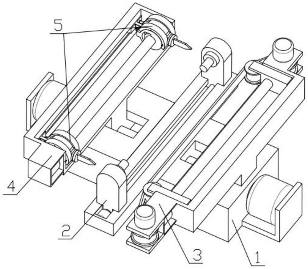
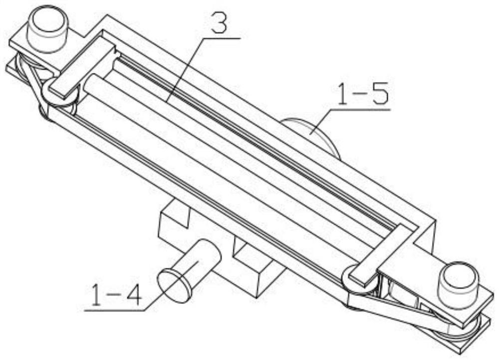
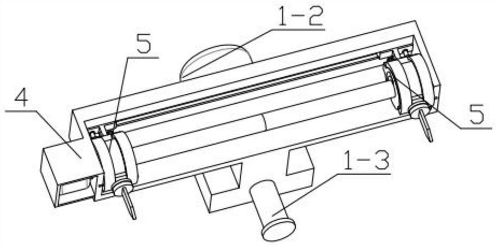
[0034] Combine below Figure 1-15 Illustrating this embodiment, a machine tool for machining parts includes a moving mechanism 1 , a workpiece fixing mechanism 2 , a grinding mechanism 3 , a machining moving mechanism 4 and a knife adjusting mechanism 5 , and the workpiece fixing mechanism 2 is fixedly installed on the moving mechanism 1 Above, the grinding mechanism 3 is threadedly connected with the moving mechanism 1 , the machining moving mechanism 4 is threadedly connected with the moving mechanism 1 , and the adjusting knife mechanism 5 is threadedly connected with the machining moving mechanism 4 .

specific Embodiment approach 2

[0036] Combine below Figure 1-15 This embodiment will be described. This embodiment will further describe the first embodiment. The workpiece fixing mechanism 2 includes a mounting horizontal plate 2-1, a motor three 2-2, a two-way threaded rod one 2-3, and a sliding seat 2-4. , fixture 2-5, internal motor 2-6, installation horizontal plate 2-1 is fixedly installed on the main base 1-1, motor three 2-2 is fixedly installed in the groove of the installation horizontal plate 2-1, motor three The output end of 2-2 is fixedly installed with a two-way threaded rod-2-3, the other end of the two-way threaded rod-2-3 is rotatably installed in the groove set on the installation horizontal plate 2-1, and the two-way threaded rod-2-3 is installed. Threaded connection with the sliding seat 2-4, the sliding seat 2-4 is slidably installed in the groove set on the installation horizontal plate 2-1, and the internal motor 2-6 is fixedly installed in the groove set on one of the sliding seats...

specific Embodiment approach 3

[0038] Combine below Figure 1-15 This embodiment will be described. This embodiment will further describe the second embodiment. The workpiece fixing mechanism 2 includes a mounting horizontal plate 2-1, a motor three 2-2, a two-way threaded rod one 2-3, and a sliding seat 2- 4. The fixture 2-5, the internal motor 2-6, the installation horizontal plate 2-1 are fixedly installed on the main base 1-1, the motor 3 2-2 is fixedly installed in the groove of the installation horizontal plate 2-1, the motor The output end of the three 2-2 is fixedly installed with a bidirectional threaded rod 1 2-3. 3. It is threadedly connected with the sliding seat 2-4, the sliding seat 2-4 is slidably installed in the groove provided on the installation horizontal plate 2-1, and the sliding seat 2-4 is fixedly installed with a clamp 2-5.


PUM


Abstract

The invention relates to a machining device, in particular to a part machining machine tool which comprises a moving mechanism, a machined part fixing mechanism, a grinding mechanism, a machining moving mechanism and a cutter adjusting mechanism. The machined part fixing mechanism is fixedly installed on the moving mechanism, the grinding mechanism is in threaded connection with the moving mechanism, the machining moving mechanism is in threaded connection with the moving mechanism, and the cutter adjusting mechanism is in threaded connection with the machining moving mechanism. According to the device, double tool bits can be used for machining the two ends of a machined material at the same time, symmetry and accuracy are guaranteed, the machining speed is increased, meanwhile, switching of a single tool and double tools can be achieved, part machining through the single tool bit is achieved, the device further has the grinding function, grinding paper can be fully utilized, and the waste phenomenon is avoided.

Description

technical field [0001] The present invention relates to a mechanical processing device, and more particularly to a machine tool for processing parts. Background technique [0002] When the machine tool is processing the parts, the workers hold the tool to process the rotating parts, which lacks precision, especially the processing of the curved parts, the precision is even more difficult to control, and the machine tools in the prior art all use a single The tool head is used to process parts, and the processing effect is low, and when multiple double heads are used for processing, it is impossible to process parts with a single tool head. SUMMARY OF THE INVENTION [0003] The main technical problem to be solved by the present invention is to provide a machine tool for machining parts. The device can use double cutter heads to simultaneously process both ends of the material to be machined, ensure symmetry and accuracy, improve machining speed, and can switch between singl...

Claims


Application Information

Patent Timeline
Patent Type & Authority Applications(China)
IPC IPC(8): B23P23/04
CPCB23P23/04
Inventor 金广辉
Owner 哈尔滨市双城区佳翀建材经销部
Why Eureka
Try Eureka