Casting cutting machine

A cutting machine and casting technology, applied in maintenance and safety accessories, metal processing machinery parts, metal processing, etc., can solve the problems of inconvenient cutting and impact, and achieve the effect of improving quality, convenient use, and increasing use rate

Active Publication Date: 2021-05-28
商都中建金马冶金化工有限公司
View PDF11 Cites 1 Cited by
  • Summary
  • Abstract
  • Description
  • Claims
  • Application Information

AI Technical Summary

Problems solved by technology

[0004] The purpose of the present invention is to solve the existing disadvantages that when cutting castings, due to the movement of the castings, it is very inconvenient to cut and the subsequent processing will be affected after cutting, and a casting cutting machine is proposed. When the cutting knife is cutting, it drives the collision plate to move upwards, thereby blocking the casting, so that the cutting knife can better cut the casting, effectively improving the quality of casting cutting, and facilitating subsequent processing

Method used


Image

  • Casting cutting machine
  • Casting cutting machine
  • Casting cutting machine

Examples


Embodiment Construction

[0019] The following will clearly and completely describe the technical solutions in the embodiments of the present invention with reference to the accompanying drawings in the embodiments of the present invention. Obviously, the described embodiments are only some, not all, embodiments of the present invention.

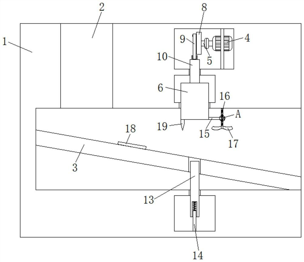
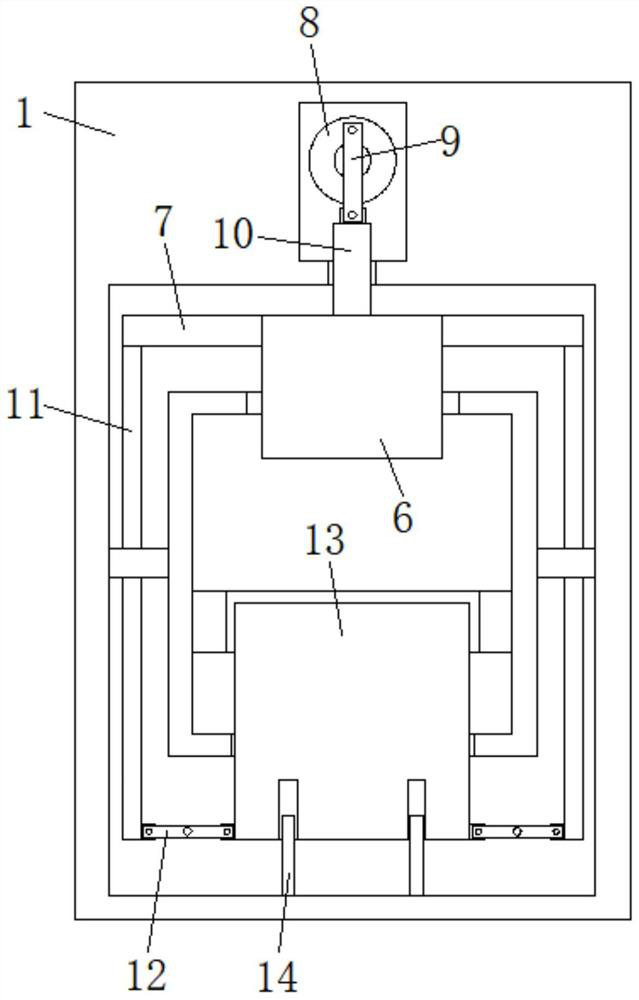
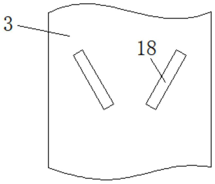
[0020] refer to Figure 1-4 , a casting cutting machine, comprising a cutting machine body 1, the cutting machine body 1 is provided with a transmission groove, the upper side wall of one side of the transmission groove is provided with a blanking port 2, and the side wall of the transmission groove is fixedly connected with a material guide plate arranged at an angle 3. There is a rectangular slot on the side wall of the upper end of the transmission slot. The side wall of the rectangular slot is fixedly connected to the limiting plate, and the limiting plate is fixedly connected to the motor 4. The motor 4 is an existing technology, so it will not be described here....


PUM


Abstract

The invention discloses a casting cutting machine. The casting cutting machine comprises a cutting machine body. A conveying groove is formed in the cutting machine body, a material falling port is formed in the upper side wall of one side of the conveying groove, the side wall of the conveying groove is fixedly connected with a material guiding plate arranged in an inclined manner, a rectangular groove is formed in the side wall of the upper end of the conveying groove, the side wall of the rectangular groove is fixedly connected with a limiting plate, and the limiting plate is fixedly connected with a motor. The output end of the motor is fixedly connected with a rotating shaft, a horizontal groove is formed in the side wall of the bottom end of the rectangular groove, a positioning block is connected to the end of the rotating shaft through a transmission mechanism, connecting plates are fixedly connected to the side walls of the two sides of the positioning block, each connecting plate is provided with a linkage mechanism, the bottom end of the positioning block penetrates through the side wall of the horizontal groove and extends into the conveying groove, a cooling mechanism is arranged at the bottom end of the positioning block. According to the casting cutting machine, the positioning block can drive an abutting plate to move upwards when a cutter conducts cutting, so that a casting is stopped, the cutter can better cut a casting, the casting cutting quality is effectively improved, and subsequent machining is facilitated.

Description

technical field [0001] The invention relates to the technical field of casting cutting, in particular to a casting cutting machine. Background technique [0002] Smelting is a refining technology, which refers to the extraction of metals from ores by means of roasting, smelting, electrolysis and the use of chemicals; reducing impurities contained in metals or increasing certain components in metals to produce the required metals . [0003] In order to improve the production efficiency of castings and make reasonable use of production resources, multiple castings can be formed at one time in the same casting mold. At this time, all castings formed in the same mold are connected together (cut pieces), so it is necessary to To cut the casting, the current cutting method is manual cutting with a hand-held cutting tool. Using this cutting method, the metal block made by smelting needs to be cut after the manufacturing is completed in order to facilitate subsequent processing. I...

Claims


Application Information

Patent Timeline
Patent Type & Authority Applications(China)
IPC IPC(8): B23Q5/34B23Q7/00B23Q7/08B23Q11/00B23Q11/10
CPCB23Q5/34B23Q7/00B23Q7/08B23Q11/005B23Q11/10
Inventor 刘日宏
Owner 商都中建金马冶金化工有限公司
Why Eureka
Try Eureka