
Automatic conveying device for hardware machining

A conveying device and material conveying technology, which is applied in the direction of transportation and packaging, conveyors, conveyor objects, etc., can solve the problems of blockage of hardware conveying devices, reduce transportation effect, and reduce conveying efficiency, so as to prevent material stacking and guarantee Transport effect, effect of improving transport efficiency

Inactive Publication Date: 2021-05-28
乌日汉
View PDF6 Cites 2 Cited by
  • Summary
  • Abstract
  • Description
  • Claims
  • Application Information

AI Technical Summary

Problems solved by technology

Hardware products are mostly not final consumer goods. During the hardware processing process, a conveying device is required for conveying operations. When the existing conveying device is in use, the hardware is easy to accumulate together, which will cause the conveying device to be blocked and affect the normal conveying operation. At the same time, the current Some conveying devices convey materials slowly, which reduces the conveying efficiency. Secondly, some hardware parts are easy to roll and fall out of the conveying device, which reduces the transportation effect.

Method used


Image

  • Automatic conveying device for hardware machining
  • Automatic conveying device for hardware machining
  • Automatic conveying device for hardware machining

Examples


Embodiment Construction

[0029] In order to make the technical means, creative features, goals and effects achieved by the present invention easy to understand, the present invention will be further described below in conjunction with specific embodiments.

[0030] In the description of the present invention, it should be noted that the terms "upper", "lower", "inner", "outer", "front end", "rear end", "both ends", "one end", "another end" The orientation or positional relationship indicated by etc. is based on the orientation or positional relationship shown in the drawings, and is only for the convenience of describing the present invention and simplifying the description, rather than indicating or implying that the referred device or element must have a specific orientation, use a specific Azimuth configuration and operation, therefore, should not be construed as limiting the invention. In addition, the terms "first" and "second" are used for descriptive purposes only, and should not be understood ...


PUM


Abstract

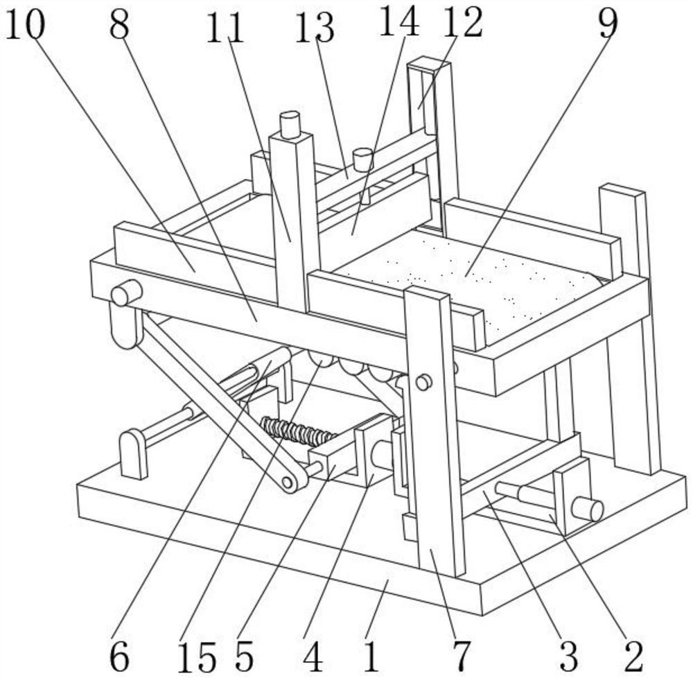
The invention discloses an automatic conveying device for hardware machining. The automatic conveying device for hardware machining comprises a base, wherein a first containing frame is fixedly installed on the middle side of the right part of the upper end of the base; a telescopic extrusion device is arranged in an inner cavity of the first containing frame; a second containing frame is fixedly installed on the middle side of the left part of the upper end of the base; a sliding extrusion device is arranged in an inner cavity of the second containing frame; a supporting device is arranged on the left part of the upper end of the base; fixing plates are fixedly installed on the front side and the rear side of the right part of the upper end of the base correspondingly; a conveying device is arranged in an inner cavity of a conveying table; a sliding device is arranged on the groove walls of two sliding grooves; and a flow dividing device is arranged in the middle of the upper end of the sliding device. According to the automatic conveying device for hardware machining provided by the invention, when an extrusion block continuously extrudes an arc-shaped block, the conveying device generates a vibration effect, and materials on the conveying device are vibrated to be in a dispersed state, so that material stacking is further prevented, and normal conveying operation is guaranteed.

Description

technical field [0001] The invention relates to the field of hardware processing equipment, in particular to an automatic feeding device for hardware processing. Background technique [0002] Hardware: traditional hardware products, also known as "hardware". Refers to the five metals of gold, silver, copper, iron, and tin. After manual processing, it can be made into works of art or metal devices such as knives and swords. Hardware in modern society is more extensive, such as hardware tools, hardware parts, daily hardware, construction hardware and security supplies. Hardware products are mostly not final consumer goods. During the hardware processing process, conveying devices are required for conveying operations. The existing conveying devices are easy to pile up when the hardware is in use, which will cause the conveying device to be blocked and affect the normal conveying operation. At the same time, Some conveying devices transport materials slowly, which reduces th...

Claims


Application Information

Patent Timeline
Patent Type & Authority Applications(China)
IPC IPC(8): B65G15/00B65G47/22
CPCB65G15/00B65G47/22
Inventor 乌日汉
Owner 乌日汉
Learn More