Chain assembly line

A technology for assembling lines and chains. It is used in cleaning devices, transportation and packaging, conveyor objects, etc. It can solve the problems of floating between the slider and the side wall of the plate cavity, the obstacle of slider lifting, and the large volume of dust particles.

Inactive Publication Date: 2021-05-28
潘新凤
View PDF13 Cites 0 Cited by
  • Summary
  • Abstract
  • Description
  • Claims
  • Application Information

AI Technical Summary

Problems solved by technology

[0004] The bearing seat is connected to the chain and moves with its transmission. When carrying the cylindrical motor shell, it usually loosens and clamps the product through the cooperation between the jacking sliders to replace the product and carry out the conveying operation. , because there are usually many dust particles in the production workshop and the volume is large, it is easy to cause floating between the slider and the side wall of the plate cavity, so that the particle dust carried by the slider will rub against the side wall during the lifting process, resulting in damage to the plate cavity , causing obstacles in the lift of the slider

Method used


Image

  • Chain assembly line
  • Chain assembly line
  • Chain assembly line

Examples


Embodiment 1

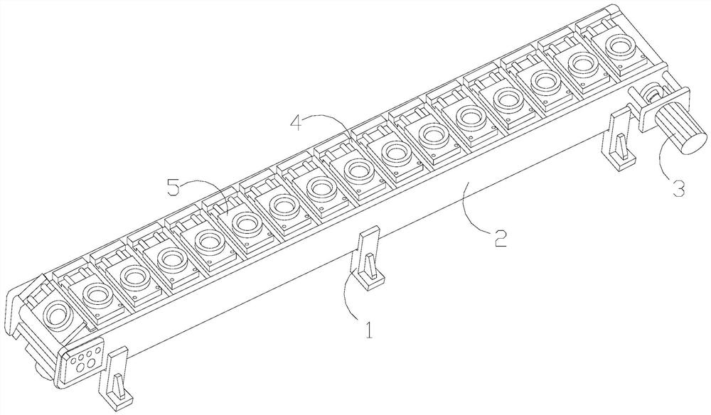
[0029] as attached figure 1 To attach Figure 6 Shown:

[0030] The invention provides a chain assembly line, the structure of which is provided with a foot base 1, a whole board 2, a driving roller 3, a chain 4, and a bearing seat 5. The foot base 1 is embedded and connected under the whole board 2, and the driving The roller 3 is installed through one side of the whole board 2, the chain 4 is movable on the top surface of the whole board 2, and the bearing seat 5 is installed on the chain 4 and movably matched.

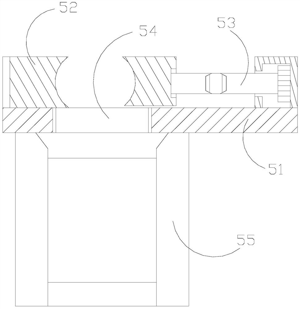
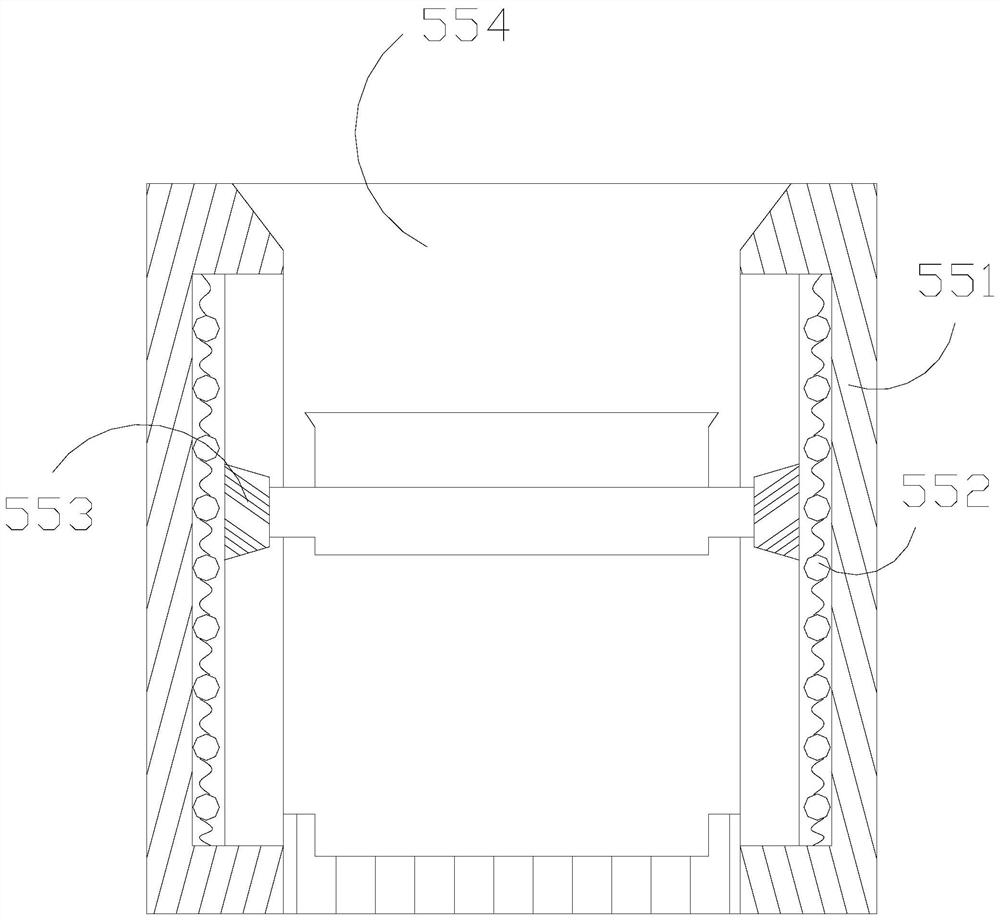
[0031] The bearing seat 5 is provided with a middle bearing plate 51, a clip seat 52, an adjusting pressure rod 53, a through-carrying cavity 54, and a lower support body 55. Cooperating with the clamping seat 52, the load-carrying chamber 54 and the middle bearing plate 51 are integrated structures and communicate with each other. The lower support body 55 is installed under the middle bearing plate 51. 54 are interconnected and coordinated in activities.

[00...

Embodiment 2

[0038] as attached Figure 7 To attach Figure 8 Shown:

[0039] Wherein, the abutting body a3 is provided with a through plate q1, an inner groove q2, a half-capsule holding block q3, and a shovel block q4. The contact block q3 is movably fitted under the shovel block q4, and the shovel block q4 is embedded in the inner groove q2 and engages in a movable manner. Two, distributed at the port positions on both sides of the through plate q1, and are in the shape of a hemisphere, made of plastic elastomer material, with excellent elastic force, the shovel block q4 snaps together under the elastic resistance of the half-capsule block q3 The port is on the side of the through plate q1, and has an inclined angle, which is convenient for removing foreign objects, and then falls out from the through plate q1 when the apex a3 is turned upside down.

[0040] Wherein, the shovel block q4 is provided with a hinge pulley w1, a solid block w2, a drop port w3, and a flow path w4. The mid...


PUM


Abstract

The invention discloses a chain assembly line. Thechain assembly line is structurally provided with foot bases, a whole plate, a driving roller, a chain and a bearing base. Sliding block bodies slide in a lifting mode under the action of a lifting power disc, no foreign object abuts against the lower end of an arc sliding body during ascending, the arc sliding body slides out through an opening in the bottom end of an outer frame, and an arc pocket spring plays a role in receiving and limiting the arc sliding body; and a touch pressing block generates downward pressing abutting force on the arc sliding body to prevent the arc sliding body from sliding into an inner cavity in the process of rubbing the side wall of a columnar plate cavity, a whole supporting section maintains the arc sliding body in an arc shape integrally, the side wall of the columnar plate cavity is in contact through the elastic toughness of a middle soft section , a side connecting diameter facilitates falling of floating dust and collection of the dust, a shovel block integrally stretches and protrudes towards a side port of a through plate, the bottom of the shovel block abuts against a half-bag abutting block, certain inclination is achieved for a solid block, attachments on the side wall of the columnar plate cavity can be conveniently shoveled away by the whole shovel block in the displacement process, shoveled materials can be conveniently discharged through a through hole structure of the through plate, and therefore the situation that dust attachments exist on the side wall of the columnar plate cavity, and consequently the displacement movement of the sliding block bodies is affected is avoided.

Description

technical field [0001] The invention belongs to the field of assembly lines, and more specifically relates to a chain assembly line. Background technique [0002] The chain assembly line uses the chain as a traction and conveying accessory, and carries out flow-through conveyance of the load through its transmission activities. The chain is the main operation workpiece of the conveyance. Different bearings. [0003] Based on the inventor's discovery above, there are following deficiencies in the existing chain assembly line: [0004] The bearing seat is connected to the chain and moves with its transmission. When carrying the cylindrical motor shell, it usually loosens and clamps the product through the cooperation between the jacking sliders to replace the product and carry out the conveying operation. , because there are usually many dust particles in the production workshop and the volume is large, it is easy to cause floating between the slider and the side wall of the...

Claims


Application Information

Patent Timeline
IPC IPC(8): B65G17/46B65G17/42B65G17/30B65G17/12B65G45/10
CPCB65G17/46B65G17/12B65G17/42B65G17/30B65G45/10
Inventor 刘月阳
Owner 潘新凤
Why Eureka
Try Eureka