Annular microstructure optical fiber for orbital angular momentum transmission and preparation method

A technology of orbital angular momentum and microstructured optical fiber, which is applied in cladding optical fiber, glass manufacturing equipment, optics, etc., can solve the problems that are difficult to realize, difficult to realize optical fiber preform production, poor refractive index, etc., and achieve the effect of reducing costs

Active Publication Date: 2021-05-28
艾菲博(宁波)光电科技有限责任公司
View PDF6 Cites 0 Cited by
  • Summary
  • Abstract
  • Description
  • Claims
  • Application Information

AI Technical Summary

Problems solved by technology

[0003] At present, there are the following problems in the proposed optical fiber structure for transmitting OAM beams: the capillary holes are arranged in a circular manner, which cannot be realized by stacking technology, and it is difficult to realize the production of meter-scale optical fiber preforms; the use of square capillary When the optical fiber is melted and stretched, all the air hole structures formed tend to be circular. Therefore, the optical fiber with square air holes is only theoretically feasible, and it is difficult to realize in the actual preparation process; the existing Although the photonic crystal fiber structure is used for reference in some technical solutions, the waveguide structure is still based on the refractive index difference produced by different materials, and the external capillary structure does not play the role of confining the waveguide. Therefore, it is urgent to study the above problems. A ring-shaped microstructure optical fiber that can be implemented and can be prepared based on the photonic crystal fiber stacking method for orbital angular momentum transmission and its preparation method to meet the needs of actual use

Method used


Image

  • Annular microstructure optical fiber for orbital angular momentum transmission and preparation method
  • Annular microstructure optical fiber for orbital angular momentum transmission and preparation method
  • Annular microstructure optical fiber for orbital angular momentum transmission and preparation method

Examples


Embodiment Construction

[0037] The following will clearly and completely describe the technical solutions in the embodiments of the present invention with reference to the accompanying drawings in the embodiments of the present invention. Obviously, the described embodiments are only some, not all, embodiments of the present invention. Based on the embodiments of the present invention, all other embodiments obtained by persons of ordinary skill in the art without creative efforts fall within the protection scope of the present invention.

[0038] It should be noted that, in the case of no conflict, the embodiments of the present invention and the features in the embodiments can be combined with each other.

[0039] The present invention will be further described below in conjunction with the accompanying drawings and specific embodiments, but not as a limitation of the present invention.

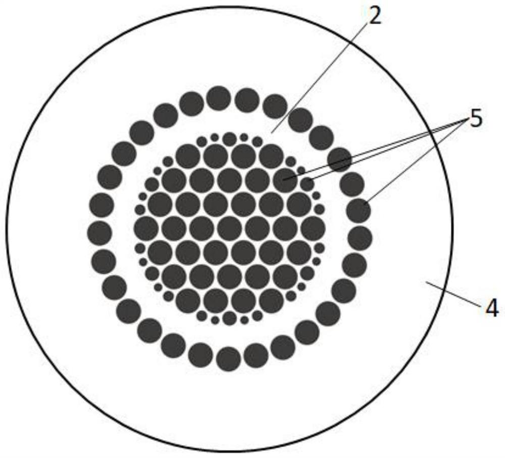
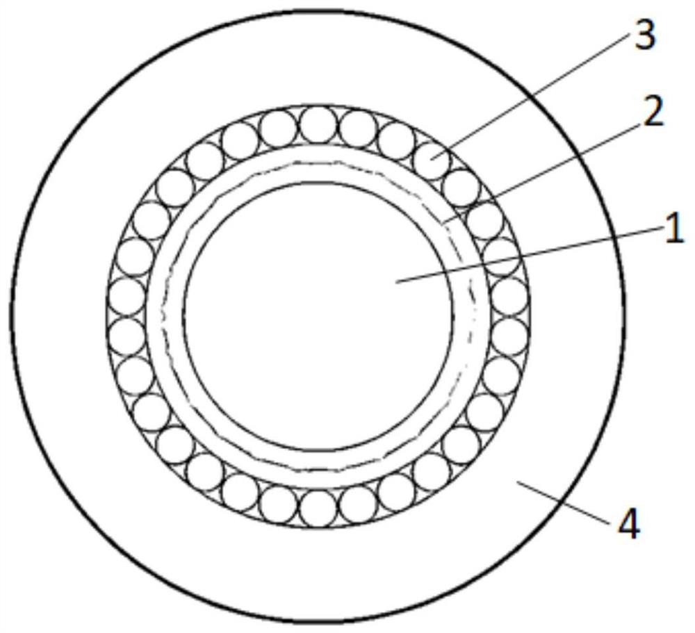
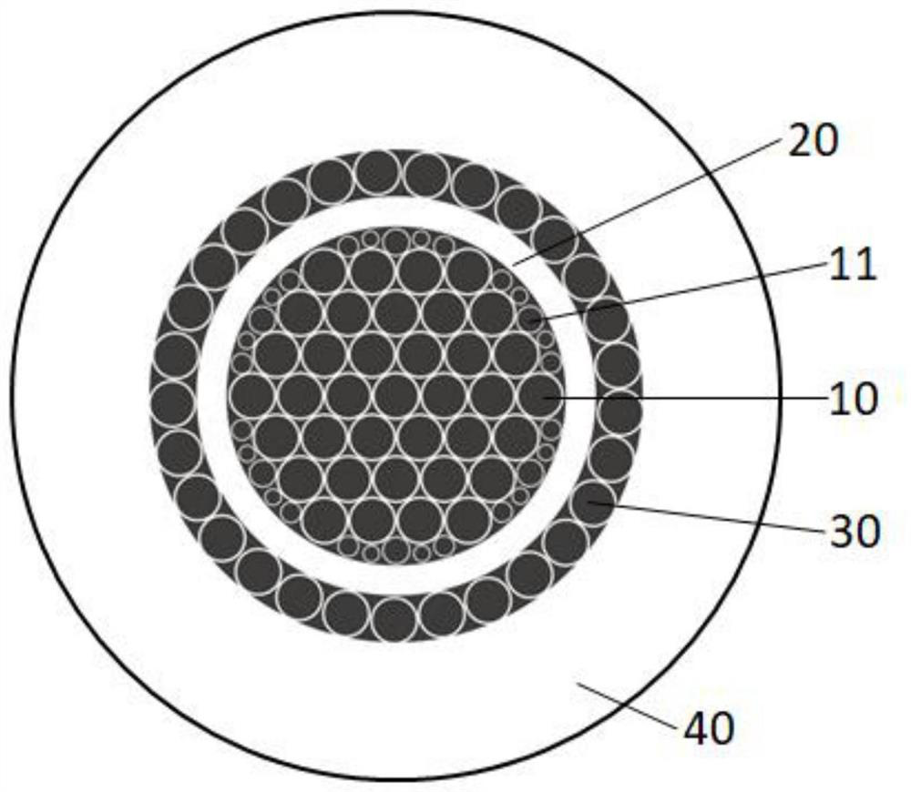
[0040] The invention provides an annular microstructure optical fiber for orbital angular momentum transmission,...


PUM

PropertyMeasurementUnit
thicknessaaaaaaaaaa

Abstract

The invention discloses an annular microstructure optical fiber for orbital angular momentum transmission and a preparation method, and belongs to the field of optical fiber communication, the annular microstructure optical fiber comprises an inner cladding region, an outer cladding region and an annular fiber core region; the inner cladding region comprises a plurality of periodically distributed air holes, the air duty ratio being 50-99%; the transmission mode of the optical waveguide is an orbital angular momentum mode, the number of transmissible modes is greater than 2, and the mode purity is greater than 90%; the inner cladding area, the annular fiber core area and the outer cladding area are made of the same material. The beneficial effects of the invention lie in that no extra doped material is needed, the cost is reduced, and the introduced air holes can play a role in constraining the waveguide; based on the stacking method of the photonic crystal fiber, the orbital angular momentum transmission microstructure fiber is no longer a theoretical idea, and the optical waveguide parameters of the microstructure fiber can be adjusted to meet the parameter requirements applied to different scenes.

Description

technical field [0001] The invention relates to the field of optical fiber communication, in particular to an annular microstructure optical fiber for orbital angular momentum transmission and a preparation method. Background technique [0002] Orbital angular momentum (OAM) is the component of the beam's angular momentum that depends on the field spatial distribution and not on the polarization state of the light. The transmission methods of OAM beams mainly include free space transmission and optical fiber transmission. Compared with free space transmission, optical fiber transmission can isolate the transmission signal from the external environment, reduce external interference, increase information capacity, and extend transmission distance. The transmission parameters of the OAM beam in the fiber have a decisive influence on the structure of the fiber, including parameters such as the number of supported OAM modes, crosstalk between modes, mode purity, and mode transmi...

Claims


Application Information

Patent Timeline
Patent Type & Authority Applications(China)
IPC IPC(8): C03B37/027C03B37/012G02B6/02
CPCC03B37/027C03B37/01211G02B6/02342Y02P40/57
Inventor 郑羽殷若琛江昕刘思迪付晓松邹琪琳
Owner 艾菲博(宁波)光电科技有限责任公司
Why Eureka
Try Eureka