Steel plate shear wall structure with semi-wrapped concrete combination column and anchoring structure thereof

A steel plate shear wall and anchoring structure technology, applied in the direction of walls, building components, building structures, etc., can solve the problems of large assembly welding workload, high welding seam quality requirements, small edge column stiffness, etc., and achieve good engineering applications. Prospects, improved mechanical properties, stable hysteretic properties

Active Publication Date: 2021-05-28
LANZHOU UNIVERSITY OF TECHNOLOGY
View PDF8 Cites 0 Cited by
  • Summary
  • Abstract
  • Description
  • Claims
  • Application Information

AI Technical Summary

Problems solved by technology

[0003] The prerequisite for the steel plate shear wall structure to give full play to the seismic performance is that the steel plate buckles in a large area and forms uniformly distributed tension bands along the diagonal direction. The restraint frame provides sufficient anchorage for the built-in steel plates. However, the rigidity of ordinary steel edge columns is small, and the large earthquake center often buckles prematurely and fails, which causes more tension bands to act on the edge restraint beams, resulting in The steel plates near the restraint column cannot be fully utilized, thus forming an "insufficient tension field", the effective anti-side area of ​​the structure is reduced, and the energy dissipation performance is difficult to fully exert
[0004] The built-in steel plate, as an important energy-dissipating component, is often connec

Method used


Image

  • Steel plate shear wall structure with semi-wrapped concrete combination column and anchoring structure thereof
  • Steel plate shear wall structure with semi-wrapped concrete combination column and anchoring structure thereof
  • Steel plate shear wall structure with semi-wrapped concrete combination column and anchoring structure thereof

Examples


Embodiment Construction

[0028] The present invention will be further explained below in conjunction with the accompanying drawings and specific embodiments. Apparently, the described embodiments are part of the embodiments of the present application, not all of them. Based on the embodiments in this application, all other embodiments obtained by persons of ordinary skill in the art without making creative efforts belong to the scope of protection of this application.

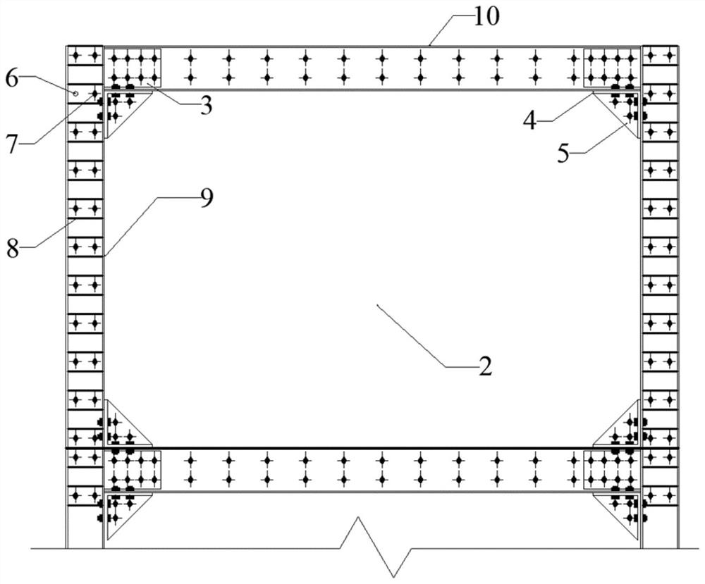
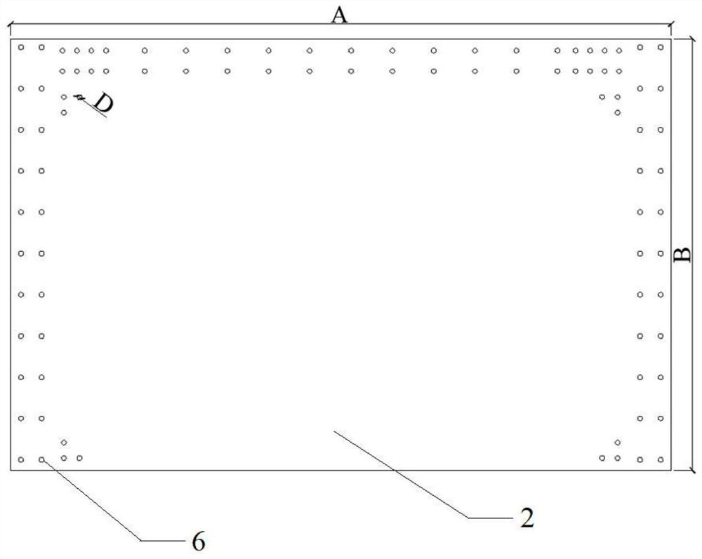
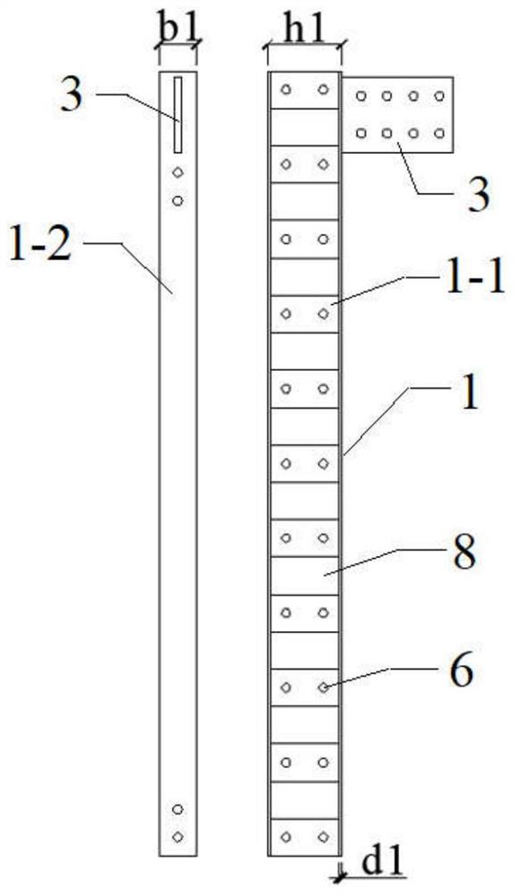
[0029] Embodiments of the present invention provide an anchoring structure for steel plate shear walls, see figure 1 , which includes two double C channel steel composite section columns 9, two double C channel steel composite section beams 10 and built-in steel plates 2, two double C channel steel composite section columns 9 and two double C channel steel composite section beams 10 An edge-constrained frame is formed by enclosing, and the double C-channel steel composite section column 9 and the double C-channel steel composite sectio...


PUM


Abstract

The invention discloses a steel plate shear wall structure with a semi-wrapped concrete combination column and an anchoring structure thereof. The steel plate shear wall structure can effectively provide an anchoring effect of an edge constraint frame of the steel plate shear wall structure on a built-in steel plate, so that a sufficient and uniform tension field is formed, the anti-seismic property of the structure is fully exerted, the bearing capacity of the structure is higher, the hysteretic behavior is more stable, and assembling is easy. The steel plate shear wall structure comprises two double-C-channel-steel combined section columns, two double-C-channel-steel combined section beams and a built-in steel plate; each of the double-C-channel-steel combined section columns and each of the double-C-channel-steel combined section beams comprises two pieces of C-shaped channel steel arranged oppositely; the edge of the built-in steel plate is clamped between the two pieces of C-shaped channel steel arranged oppositely; the edge of the built-in steel plate is anchored and connected with the C-shaped channel steel through high-strength bolts; and concrete is poured into steel grooves of the two pieces of oppositely-arranged C-shaped channel steel of the double-C-channel-steel combined section columns, so that the semi-wrapped concrete combination column is formed.

Description

technical field [0001] The invention belongs to the field of building construction and structure anti-seismic, and in particular relates to a steel plate shear wall structure with a semi-wrapped concrete composite column and an anchoring structure thereof. Background technique [0002] The structural unit of the steel plate shear wall is mainly composed of three parts: the embedded steel plate, the vertical edge restraint member and the horizontal edge restraint member. The enlarged steel plate is prone to local buckling, and forms tension bands along the diagonal direction, and the bulging tension bands play the role of diagonal bracing, which improves the bearing capacity of the structure. [0003] The prerequisite for the steel plate shear wall structure to give full play to the seismic performance is that the steel plate buckles in a large area and forms uniformly distributed tension bands along the diagonal direction. The restraint frame provides sufficient anchorage f...

Claims


Application Information

Patent Timeline
IPC IPC(8): E04B2/60E04B1/98E04H9/02E04B1/94
CPCE04B2/60E04B1/98E04H9/02E04B1/94
Inventor 殷占忠冯大哲卯永生杨博陈程悦王兆辉延路瑶吕文辉朱有涛刘星辰刘岸飞李鑫炜
Owner LANZHOU UNIVERSITY OF TECHNOLOGY
Why Eureka
Try Eureka