Cutting transmission main body part structure

A technology of the main body and transmission mechanism, which is applied in the direction of the transmission box, transmission parts, driving device, etc., and can solve complex problems. The center of gravity of the fixed part and the swinging part is relatively biased towards the coal wall, the front and rear width of the fixed part is too large, and the space for downhole transportation Limitations and other issues, to achieve the effect of simple front-stage cutting transmission mechanism, light weight, and improved adaptability

Pending Publication Date: 2021-05-28
SHANGHAI TIANDI MINING EQUIP TECH CO LTD +2
View PDF0 Cites 0 Cited by
  • Summary
  • Abstract
  • Description
  • Claims
  • Application Information

AI Technical Summary

Problems solved by technology

On this basis, some designs consider the structure of the loading channel on the side of the drum, and set a part of the transmission of the fixed part above the conveyor trough, which not only affects the coal passing space, but also the front and rear width of the fixed part is too large, which makes it difficult to transport in the downhole. The space is limited; some also set the power and main deceleration part on the coal wall side in front of the conveying trough (that is, between the left and right rollers). Although the mining height can be lower, the transmission is relatively complicated, and the center of gravity of the fixed part and the swing part are relatively biased. The coal wall has a certain adverse effect on the operation of the whole machine, especially in the condition of the undercut working face.

Method used


Image

  • Cutting transmission main body part structure
  • Cutting transmission main body part structure
  • Cutting transmission main body part structure

Examples


Embodiment Construction

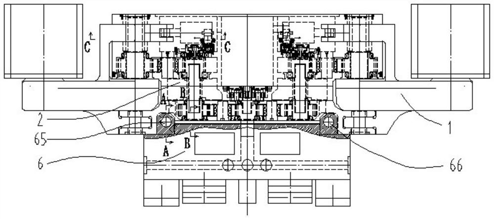
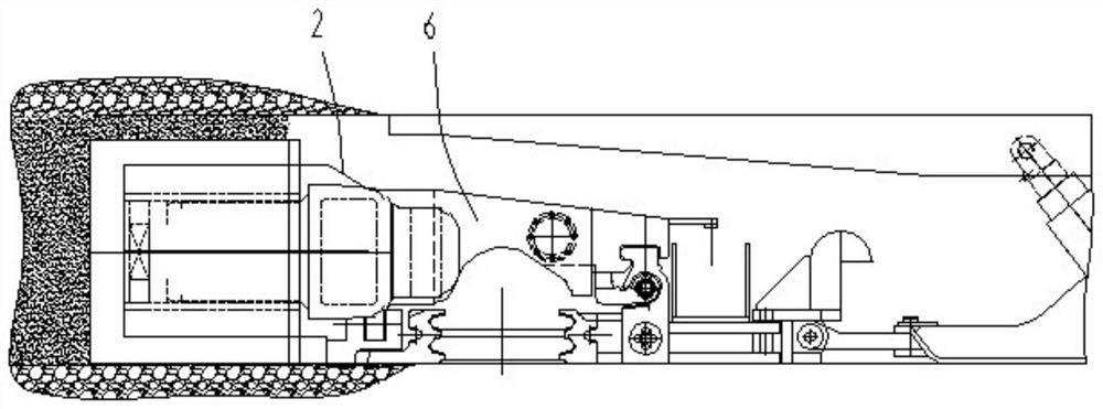
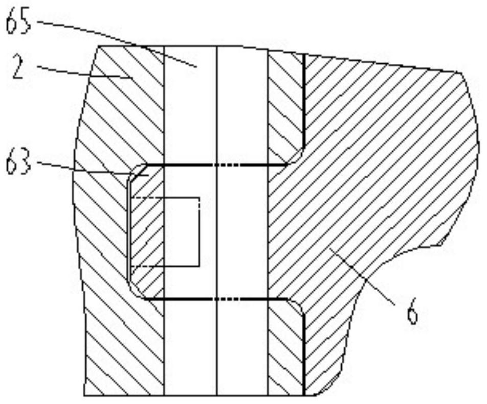
[0047] The invention discloses a cutting transmission main part structure, such as Figure 1-10 As shown, a fixed reduction box 2 is included, and the fixed reduction box includes a fixed reduction box housing 21 and an oil cylinder 4, a cutting motor 7 and a front-stage cutting transmission mechanism arranged in the fixed reduction box housing. The front-stage cutting transmission mechanism includes a high-speed planetary mechanism 81, a central gear 83, and two sets of left and right gear reduction mechanisms that are connected in sequence. The central gear and the left and right two sets of gear reduction mechanisms form a multi-stage large reduction ratio transmission mechanism. The cutting motor 7 and the high-speed planetary mechanism 81 each have one, and the output shaft of the cutting motor extends backward and is coaxially connected to the power input end of the high-speed planetary mechanism. The central gear is meshed with the left and right two groups of gear red...


PUM


Abstract

The invention relates to a cutting transmission main body part structure which comprises a fixed reduction gearbox shell, and an oil cylinder, a cutting motor and a preceding-stage cutting transmission mechanism which are positioned in an inner cavity of the fixed reduction gearbox shell; the preceding-stage cutting transmission mechanism comprises a high-speed-stage planetary mechanism, a central gear, a left and a right groups of gear reduction mechanisms which are in transmission connection in sequence; each gear reduction mechanism comprises a first fixed shaft gear transmission mechanism and a second fixed shaft gear transmission mechanism which are connected through a spline; the first fixed shaft gear transmission mechanisms and the second fixed shaft gear transmission mechanisms extend from the middle of the fixed reduction gearbox shell to the left side and the right side according to the power transmission sequence; the second fixed shaft gear transmission mechanisms are located in front of the first fixed shaft gear transmission mechanisms; the oil cylinder is located in front of the second fixed shaft gear transmission mechanisms; and a gap bridge structure installation connector is arranged at the rear end of the fixed reduction gearbox shell. According to the cutting transmission main body part structure, the problems of loading channels and underground transportation can be solved, the transmission mechanism is simple, and the overall layout is beneficial to improvement of the gravity center of a whole coal mining machine.

Description

technical field [0001] The invention relates to a cutting transmission main part structure, which is suitable for coal shearers with a short fuselage and a wide mining range. Background technique [0002] In the mining of thin coal seam lower limit or extremely thin coal seam conditions, in order to improve the adaptability of the cutting swing rocker to the coal seam, the cutting transmission system is usually set to consist of two parts: the fixed part of the short structure with power and the swing part of the output power . On this basis, some designs consider the structure of the loading channel on the side of the drum, and set a part of the fixed part of the transmission above the conveyor trough, which not only affects the coal passing space, but also the front and rear width of the fixed part is too large, which makes it difficult to transport in the mine. The space is limited; some also set the power and main deceleration part on the coal wall side in front of the ...

Claims


Application Information

Patent Timeline
Patent Type & Authority Applications(China)
IPC IPC(8): E21C31/02F16H57/02F16H57/021F16H57/023F16H57/025F16H57/029F16H57/08
CPCE21C31/02F16H57/02F16H57/021F16H57/023F16H57/025F16H57/029F16H57/08F16H2057/02034F16H2057/02069F16H2057/02086
Inventor 史春祥王振乾章立强翟雨生郭岱董超金丹华高占峰沈胜超胡滔胡璟宋振顾恩洋丁海春李庆亮刘峰乐南更王灿魏升刘振高振帮全保朝
Owner SHANGHAI TIANDI MINING EQUIP TECH CO LTD
Why Eureka
Try Eureka