Quick connecting joint for disc valve operating device of water-turbine generator set and mounting method
A generator set and quick connection technology, which is applied in the direction of hydroelectric power generation, threaded connection, engine components, etc., can solve the problems of easy oil leakage, inconvenient disassembly, insufficient sealing, etc., and achieve the effect of quick connection
- Summary
- Abstract
- Description
- Claims
- Application Information
AI Technical Summary
Problems solved by technology
Method used
Image

Examples
Embodiment 1
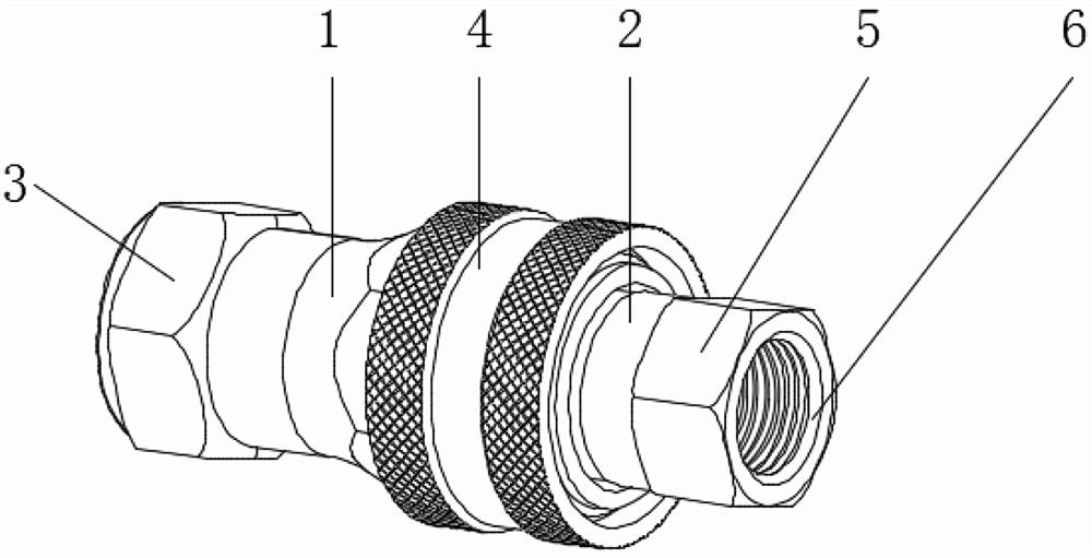
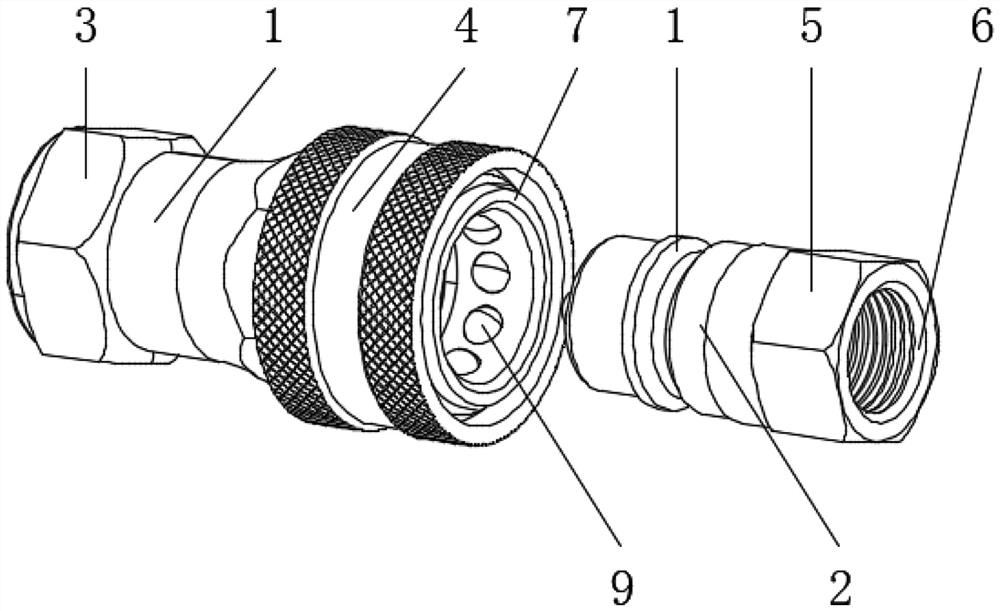
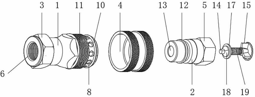
[0032] see Figure 1-5 , the quick-connect connector of the disc-type valve operating device of the hydro-generator set, including a male connector 1 and a female connector 2, the end of the male connector 1 is provided with a first connecting nut 3, and the end of the female connector 2 is provided with a second connecting nut 5 , the inside of the first connecting nut 3 and the second connecting nut 5 are provided with a sealing washer 6; the surface of the male connector 1 is provided with an anti-slip buckle 4 at the connection point corresponding to the female connector 2, and the front end of the male connector 1 corresponds to The inner side of the anti-slip buckle 4 is provided with a connecting plate 7, the outer surface of the connecting plate 7 is provided with a through hole 8, the inner side of the through hole 8 is provided with a ball 9, and the outer surface of the connecting plate 7 is provided with a connecting plate 7 corresponding to the inner side of the an...
Embodiment 2
[0041] The installation method of the quick connection joint of the disc valve operating device of the hydroelectric generating set includes the following steps:
[0042] Step 1: Use the first connecting nut 3 to cooperate with the sealing washer 6 to install the male joint 1 on the matching flange surface of the disc valve;
[0043] Step 2: Use the second connecting nut 5 to cooperate with the sealing washer 6 to install the female joint 2 on one end of the mobile oil pump hose;
[0044] Step 3: Insert the female connector 2 into the inside of the male connector 1, and fasten the female connector 2 with the anti-slip buckle 4;
[0045] Step 4: Check the joint for oil leakage.
[0046] In the third step, during the plugging process, the anti-slip buckle 4 is first slid towards the rear end, so that the anti-slip buckle 4 compresses the first spring 11, so that the anti-slip buckle 4 slides along the surface of the connecting ring 10, and at this time the connecting plate 7 T...
PUM
 Abstract
Description
Claims
Application Information
 - Generate Ideas
- Intellectual Property
- Life Sciences
- Materials
- Tech Scout
- Unparalleled Data Quality
- Higher Quality Content
- 60% Fewer Hallucinations
Browse by: Latest US Patents, China's latest patents, Technical Efficacy Thesaurus, Application Domain, Technology Topic, Popular Technical Reports.
© 2025 PatSnap. All rights reserved.Legal|Privacy policy|Modern Slavery Act Transparency Statement|Sitemap|About US| Contact US: help@patsnap.com