Soil real-time monitoring system based on intelligent agricultural planting

A real-time monitoring system and agricultural technology, applied in the direction of measuring devices, engine frames, measuring instrument components, etc., can solve the problems of inconvenient control box installation and high cost

Pending Publication Date: 2021-05-28
山东钟金燕家纺有限公司 +3
View PDF1 Cites 5 Cited by
  • Summary
  • Abstract
  • Description
  • Claims
  • Application Information

AI Technical Summary

Problems solved by technology

[0007] In view of the deficiencies in the existing technology, the purpose of the present invention is to provide a real-time soil monitoring system based on intelligent agricultural planting, which solves the problems that it takes a lot of effort to fix and it is inconvenient to install the control box

Method used


Image

  • Soil real-time monitoring system based on intelligent agricultural planting
  • Soil real-time monitoring system based on intelligent agricultural planting
  • Soil real-time monitoring system based on intelligent agricultural planting

Examples


Embodiment 1

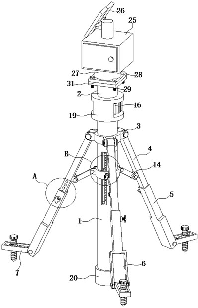
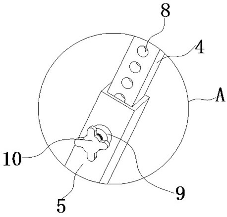
[0037] see Figure 1-9, the present invention provides a technical solution: a real-time soil monitoring system based on intelligent agricultural planting, including a lower pillar 1, an upper pillar 2 and a control box 25, and the outside of the top of the lower pillar 1 is fixedly installed with a mounting plate 3, and the mounting plate 3 There is a first adjusting rod 4 hinged inside, the bottom of the first adjusting rod 4 is sleeved with a second adjusting rod 5, the bottom of the second adjusting rod 5 is fixedly installed with a positioning device 7, and the inside of the lower pillar 1 is sleeved with an adjusting screw 11. The limit slider 12 is sleeved on the outside of the adjustment screw 11, and the side of the limit slider 12 away from the adjustment screw 11 is fixedly installed with a movable disc 13, and the outside of the movable disc 13 is hinged with a transmission rod 14, which is far away from the movable One side of the disk 13 is hingedly connected wit...

Embodiment 2

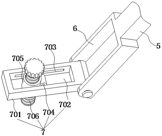
[0040] Such as Figure 1-9 As shown, on the basis of Embodiment 1, the present invention provides a technical solution: the positioning device 7 includes a movable frame 701, and the inside of the movable frame 701 is provided with a groove 702, and both sides of the inner wall of the groove 702 are provided with slide grooves 703 , a rotating shaft 704 is movably installed inside the chute 703 , the outer portion of the rotating shaft 704 is sleeved with a connecting sleeve 705 , and the inner portion of the connecting sleeve 705 is sleeved with a fixed pile 706 .

[0041] In this embodiment, the bottom of the fixed pile 706 is a sharp point, which is conducive to drilling the fixed pile 706 into the ground, which has a labor-saving effect and prevents the operator from spending a lot of effort. When fixing the device, the connecting sleeve 705 must be rotated , align the tip of the bottom of the fixed pile 706 with the ground, and pull the fixed pile 706 along the chute 703,...

Embodiment 3

[0043] Such as Figure 1-9 As shown, on the basis of Embodiment 1 and Embodiment 2, the present invention provides a technical solution: a placement groove 6 is opened on the side of the second adjustment rod 5 away from the lower pillar 1, and the positioning device 7 is located inside the placement groove 6 .

[0044] In this embodiment, by setting the placement groove 6, when the device is not in use, the entire positioning device 7 can be received into the placement groove 6, avoiding accidental injury to the operator by the tip of the fixing pile 706 in the positioning device 7, and at the same time The whole positioning device 7 is accommodated, which is convenient for the operator to move.


PUM


Abstract

The invention discloses a soil real-time monitoring system based on intelligent agricultural planting. The system involves a lower supporting column, an upper supporting column and a control box, wherein a mounting disc is fixedly mounted outside the top of the lower supporting column, first adjusting rods are hinged to the interior of the mounting disc, second adjusting rods sleeve the bottoms of the first adjusting rods, a positioning device is fixedly mounted at the bottoms of the second adjusting rods, a movable disc is fixedly mounted on the side, away from an adjusting screw, of a limiting sliding block, an adjusting block is fixedly mounted at the top of the adjusting screw, a temperature sensor is fixedly mounted at one end of the bottom of a lifting plate, and a humidity sensor is fixedly mounted at the end, away from the temperature sensor, of the bottom of the lifting plate. Through the arrangement of the adjusting screw, the limiting sliding block, a strip-shaped limiting groove, a movable disc and a transmission rod, the positions of the plurality of first adjusting rods and the plurality of second adjusting rods are changed simultaneously, an operator is prevented from repeatedly operating the first adjusting rods and the second adjusting rods, the device is conveniently fixed by the operator, and use by the operator is facilitated.

Description

technical field [0001] The invention belongs to the technical field of agricultural monitoring, and in particular relates to a real-time soil monitoring system based on intelligent agricultural planting. Background technique [0002] Soil is one of the basic elements of terrestrial ecosystems and one of the material foundations for human survival. Soil environmental conditions are not only directly related to ecological security and human health, but also directly related to the yield, quality and safety of agricultural products. In recent years, due to the rapid development of polymer chemistry, analytical chemistry, physical science, biotechnology and other sciences, it has been widely used in soil monitoring. With the development of science and technology, as well as the research and development and synthesis of materials, in the process of agricultural production and planting, crops of different seasons can be planted at any time according to people's needs, and suitable...

Claims


Application Information

Patent Timeline
Patent Type & Authority Applications(China)
IPC IPC(8): F16M11/04F16M11/18F16M11/22F16M7/00G01D11/30
CPCF16M7/00F16M11/046F16M11/18F16M11/22G01D11/30
Inventor 张信甫袁鹏飞曹志红钟金燕吴建梅
Owner 山东钟金燕家纺有限公司
Why Eureka
Try Eureka