System and method for detecting air leakage rate of flue gas heat exchanger of desulfurization device of thermal power plant
A technology of flue gas heat exchanger and desulfurization device, which can be used in the direction of measuring the acceleration and deceleration rate of fluid, using liquid/vacuum degree for liquid tightness measurement, etc., which can solve problems such as troublesome manual insertion and extraction of hoses
- Summary
- Abstract
- Description
- Claims
- Application Information
AI Technical Summary
Problems solved by technology
Method used
Image

Examples
Embodiment 1
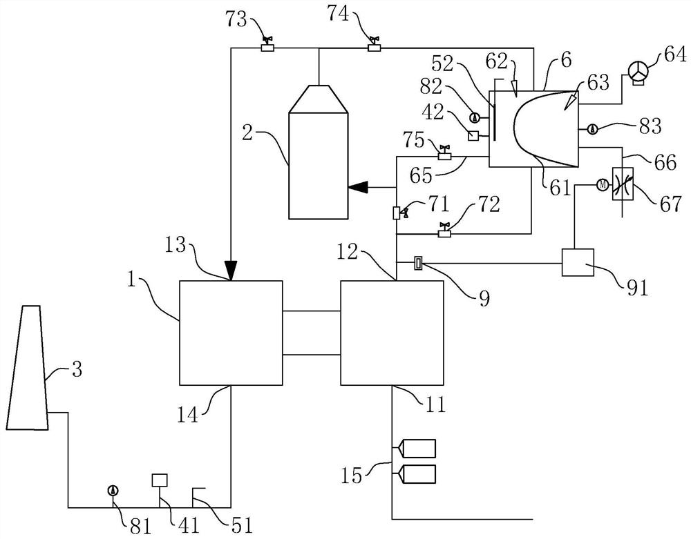
[0038] refer to figure 1, this embodiment discloses a detection system for the air leakage rate of a flue gas heat exchanger in a thermal power plant desulfurization device, including a heat exchanger 1, an absorption tower 2 and a chimney 3, the heat exchanger 1 is a rotary flue gas heat exchanger 1, and the heat exchange The device 1 includes a hot air inlet 11, a hot air outlet 12, a cold air inlet 13, and a cold air outlet 14. The hot air inlet 11 is connected to a raw flue gas pipeline 15. The hot air inlet 11 enters the original flue gas with a higher temperature and flows out from the hot air outlet 12. The hot air outlet 12 is connected to the inlet of the absorption tower 2, so that the original flue gas is absorbed in the absorption tower 2, and the outlet of the absorption tower 2 is connected to the cold air inlet 13, so that the purified flue gas in the absorption tower 2 enters the heat exchanger 1, the heat of the original flue gas is transferred to the purified...
Embodiment 2
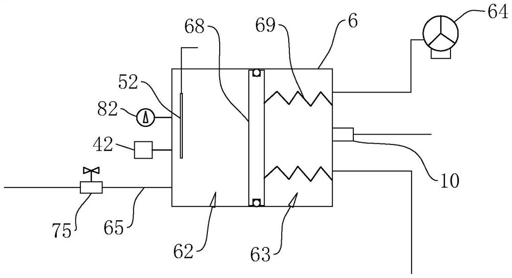
[0045] refer to figure 2 , this embodiment discloses a detection system for the air leakage rate of the flue gas heat exchanger of a desulfurization device in a thermal power plant. Cooperating with each other, a gas distribution chamber 62 and a pressure regulating chamber 63 are respectively formed on both sides of the piston 68 . A distance measuring sensor 10 is arranged on a side wall of the pressure regulating chamber 63 , and the distance of the piston 68 is measured by the distance measuring sensor 10 , so that the volume of the pressure regulating chamber 63 can be detected. A plurality of extension springs 69 are arranged on the side of the piston 68 located in the pressure regulating chamber 63 , one end of the extension spring 69 is fixed on the piston 68 , and the other end is fixed on the gas distribution box 6 .
PUM
 Abstract
Description
Claims
Application Information
 - R&D
- Intellectual Property
- Life Sciences
- Materials
- Tech Scout
- Unparalleled Data Quality
- Higher Quality Content
- 60% Fewer Hallucinations
Browse by: Latest US Patents, China's latest patents, Technical Efficacy Thesaurus, Application Domain, Technology Topic, Popular Technical Reports.
© 2025 PatSnap. All rights reserved.Legal|Privacy policy|Modern Slavery Act Transparency Statement|Sitemap|About US| Contact US: help@patsnap.com