
Groove type field effect transistor structure and preparation method thereof

A field-effect transistor and trench-type technology, which is applied in semiconductor/solid-state device manufacturing, semiconductor devices, electrical components, etc., can solve the problems that the device cell size is difficult to continue to reduce, and the device preparation process is complicated, so as to reduce the trench Effects of resistance and characteristic on-resistance, increase in cell density, and stability of electrical parameters

Active Publication Date: 2021-05-28
CHINA RESOURCES MICROELECTRONICS (CHONGQING) CO LTD
View PDF2 Cites 2 Cited by
  • Summary
  • Abstract
  • Description
  • Claims
  • Application Information

AI Technical Summary

Problems solved by technology

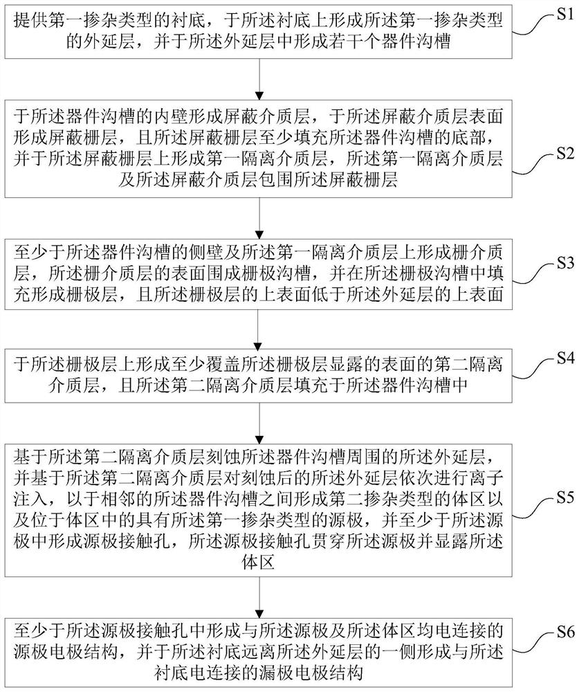
[0005] In view of the above-mentioned shortcomings of the prior art, the purpose of the present invention is to provide a trench type field effect transistor structure and its preparation method, which is used to solve the problem of complex device preparation process and difficulty in reducing the size of device cells in the prior art. And other issues

Method used


Image

  • Groove type field effect transistor structure and preparation method thereof
  • Groove type field effect transistor structure and preparation method thereof
  • Groove type field effect transistor structure and preparation method thereof

Examples


Embodiment Construction

[0092] Embodiments of the present invention are described below through specific examples, and those skilled in the art can easily understand other advantages and effects of the present invention from the content disclosed in this specification. The present invention can also be implemented or applied through other different specific implementation modes, and various modifications or changes can be made to the details in this specification based on different viewpoints and applications without departing from the spirit of the present invention.

[0093] For example, when describing the embodiments of the present invention in detail, for the convenience of explanation, the cross-sectional view showing the device structure will not be partially enlarged according to the general scale, and the schematic diagram is only an example, which should not limit the protection scope of the present invention. In addition, the three-dimensional space dimensions of length, width and depth sho...


PUM

PropertyMeasurementUnit
thicknessaaaaaaaaaa

Abstract

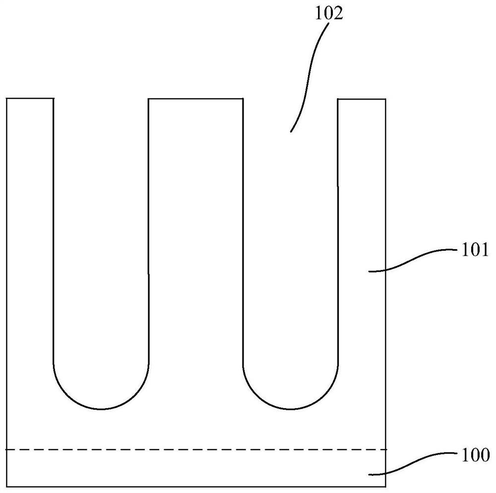
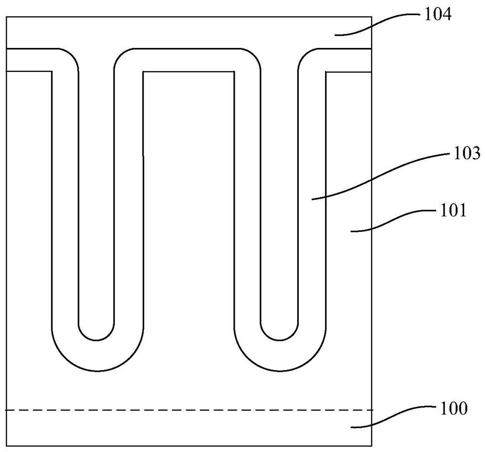
The invention provides a groove type field effect transistor structure and a preparation method thereof. The preparation method comprises the steps: providing a substrate, forming an epitaxial layer, forming a device groove in the epitaxial layer, and forming a shielding dielectric layer, a shielding gate layer, a first isolation dielectric layer, a gate dielectric layer, a gate layer, a second isolation dielectric layer, a body region, a source electrode, a source electrode contact hole, a source electrode structure and a drain electrode structure. In the preparation process of the groove type field effect transistor structure, a self-alignment process is adopted, so that the pitch of a cell unit is not limited by the exposure capability of a photoetching machine and the alignment precision of the photoetching machine, the pitch of the cell unit of a device can be further reduced, the cell density is improved, the channel resistance of the device is reduced, and a device structure with stable electrical parameters and low characteristic on-resistance is obtained; by arranging a T-shaped source electrode structure, the contact area between a source electrode structure and a source and the contact area between the source electrode structure and the body region are increased, so that the contact resistance of the source can be effectively reduced, and the avalanche tolerance of the device is improved.

Description

technical field [0001] The invention relates to power semiconductor technology, in particular to a trench type field effect transistor structure and a preparation method thereof. Background technique [0002] Shielded gate trench MOSFET devices have the advantages of lower on-resistance and faster switching speed than traditional trench MOSFETs, and have a wide range of applications, including switching power supplies, AC-AC conversion, motor control, radio frequency communications, uninterruptible power supplies, Inverter and other fields. In order to obtain a high conversion efficiency application system, it is necessary to continuously reduce the switching loss and conduction loss of the shielded gate trench MOSFET. Reducing the conduction loss means reducing the characteristic on-resistance of the shielded gate trench MOSFET. [0003] Reducing the device cell size (Pitch) and increasing the cell density is the most effective way to reduce the characteristic on-resistanc...

Claims


Application Information

Patent Timeline
Patent Type & Authority Applications(China)
IPC IPC(8): H01L21/336H01L21/28H01L29/417H01L29/423H01L29/78
CPCH01L29/66666H01L29/7827H01L29/401H01L29/41741H01L29/4236H01L29/7813H01L29/407H01L29/41766H01L29/66734H01L29/66727H01L29/66719H01L29/1095H01L29/66712H01L29/7802H01L29/41725H01L29/66621H01L29/0696H01L21/26513
Inventor 姚鑫焦伟刘华瑞吕平
Owner CHINA RESOURCES MICROELECTRONICS (CHONGQING) CO LTD
Learn More