
Uniform impedance stub loaded suspended strip line cavity combiner

A technology of uniform impedance and combiner, used in circuits, waveguide devices, electrical components, etc., can solve problems such as increased debugging costs, different two-way debugging methods, and complex processing.

Active Publication Date: 2021-05-28
NANTONG UNIVERSITY +2
View PDF9 Cites 0 Cited by
  • Summary
  • Abstract
  • Description
  • Claims
  • Application Information

AI Technical Summary

Problems solved by technology

However, its disadvantages are: the high-frequency and low-frequency channels adopt different design methods, so the two-way debugging methods are different, so the design is more complicated, and the debugging cost is increased; the partition wall between the two channels is connected with the shell, and the processing Compared with this design, it is more complex

Method used


Image

  • Uniform impedance stub loaded suspended strip line cavity combiner
  • Uniform impedance stub loaded suspended strip line cavity combiner
  • Uniform impedance stub loaded suspended strip line cavity combiner

Examples


Embodiment Construction

[0035] The present invention will be further described below in conjunction with the accompanying drawings and specific embodiments.

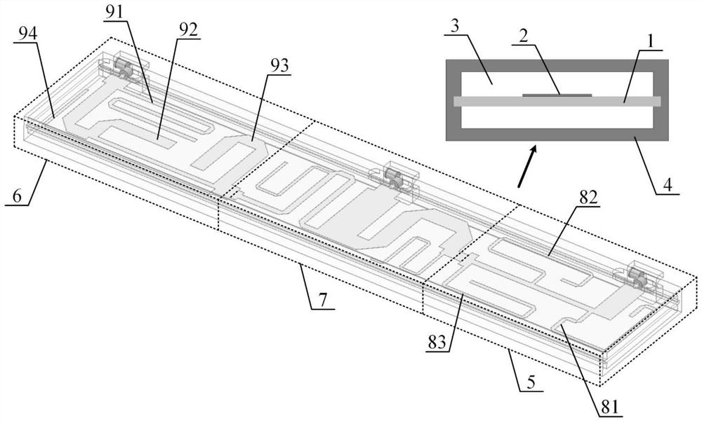
[0036] Such as figure 1 As shown, in this example, a suspended strip line cavity combiner with uniform impedance stub loading, a hollow metal cavity 4, a dielectric substrate 1 suspended and fixed in the metal cavity 4, and a substrate exposed to the air 3 above it The suspended stripline circuit 2, the suspended stripline circuit 2 includes a (7033MHz-798MHz) low-pass filter circuit 5, a (885MHz-960MHz) high-pass filter circuit 6 and a combining circuit 7. The low-pass filter circuit 5 includes a low-frequency input port, a low-frequency output port, a single π1-type structural unit, and a uniform impedance open-circuit stub 83 loaded on the low-frequency transmission line between the π1-type structural unit and the combining circuit 7. The uniform impedance open-circuit stub 83 makes A third zero point is generated in the low frequency band,...


PUM


Abstract

The invention provides a uniform impedance stub loaded suspended strip line cavity combiner, which comprises a metal cavity, a dielectric substrate and a suspended strip line circuit, wherein the dielectric substrate and the suspended strip line circuit are arranged in the metal cavity, the suspended strip line circuit comprises a low-pass filter circuit, a high-pass filter circuit and a combining circuit, the low-pass filter circuit comprises a single pi 1 type structure unit and a uniform impedance open-circuit stub loaded on a low-frequency transmission line between the pi 1 type structure unit and the combining circuit so as to generate a third zero point located on the right side of the two zero points of the pi 1 type structure unit in a low-frequency band, the high-pass filter circuit comprises two cascaded pi 2 type structural units, and the pole of each pi 2 type structural unit is located between the two zero points of the pi 2 type structural unit. According to the invention, the position of a zero pole can be flexibly regulated and controlled by adjusting the parameter value of a pi type structure unit, so that a good roll-off characteristic is generated; and in the design, non-equal-length uniform impedance stub loading and non-equal-length main line length are used, so that the size of the circuit can be reduced, and the circuit is simpler and lighter.

Description

technical field [0001] The invention relates to the technical field of combiners, in particular to a combiner with a suspended strip line cavity loaded by unequal-length uniform impedance stubs. Background technique [0002] At present, the known microstrip combiners loaded with open stubs of radio frequency signals have mostly the same width as the stubs and the main line, and the wiring area is relatively large, which is not suitable for the miniaturization of combiners in the base stations of most mobile communication systems. , at the same time, the open-circuit stub impedance of many suspended strip cavity combiners is non-uniform, and the design is relatively complicated. [0003] After searching, it is found that the patent CN 208298987 U discloses a dual-frequency cavity combiner, which includes a fifth-order interdigitated bandpass filter and a suspended stripline low-pass filter. The two filters are connected. However, its disadvantages are: the high-frequency an...

Claims


Application Information

Patent Timeline
IPC IPC(8): H01P1/213H01P11/00
CPCH01P1/213H01P11/00
Inventor 陈建新曹帅华柯彦慧杨汶汶符小东揭水平徐翠王学仁
Owner NANTONG UNIVERSITY
Learn More