
Radiating element for antenna and antenna comprising same

A radiating element and antenna technology, applied in the field of communications, can solve the problems of poor beam stability, large volume, and narrow working bandwidth, and achieve the effect of achieving precision and improving radiation performance.

Pending Publication Date: 2021-05-28
PROSE TECH CO LTD
View PDF0 Cites 0 Cited by
  • Summary
  • Abstract
  • Description
  • Claims
  • Application Information

AI Technical Summary

Problems solved by technology

[0003] It is difficult to match the microstrip patch radiating element, and its working bandwidth is narrow, so it is difficult for the microstrip patch radiating element to meet the broadband requirements of the existing 4G and 4G+ communications
[0004] Symmetrical dipole radiation beams are susceptible to interference and have poor beam stability in the broadband range
[0005] Although the existing four-point fed bowl-shaped radiating element overcomes the above-mentioned shortcomings of the microstrip patch radiating element and the symmetrical dipole, such a bowl-shaped radiating element has a large volume and consumes a lot of materials, so that such a Bowl-shaped radiating elements are expensive to manufacture and inconvenient to install

Method used


Image

  • Radiating element for antenna and antenna comprising same
  • Radiating element for antenna and antenna comprising same
  • Radiating element for antenna and antenna comprising same

Examples


Embodiment Construction

[0036] In the following detailed description of the preferred embodiments, reference is made to the accompanying drawings which form a part of this disclosure. The accompanying drawings show, by way of example, specific embodiments in which the disclosure can be practiced. The illustrated embodiments are not intended to be exhaustive of all embodiments according to the present disclosure. It is to be understood that other embodiments may be utilized and structural or logical changes may be made without departing from the scope of the present disclosure. Accordingly, the following detailed description is not limiting, and the scope of the present disclosure is defined by the appended claims.

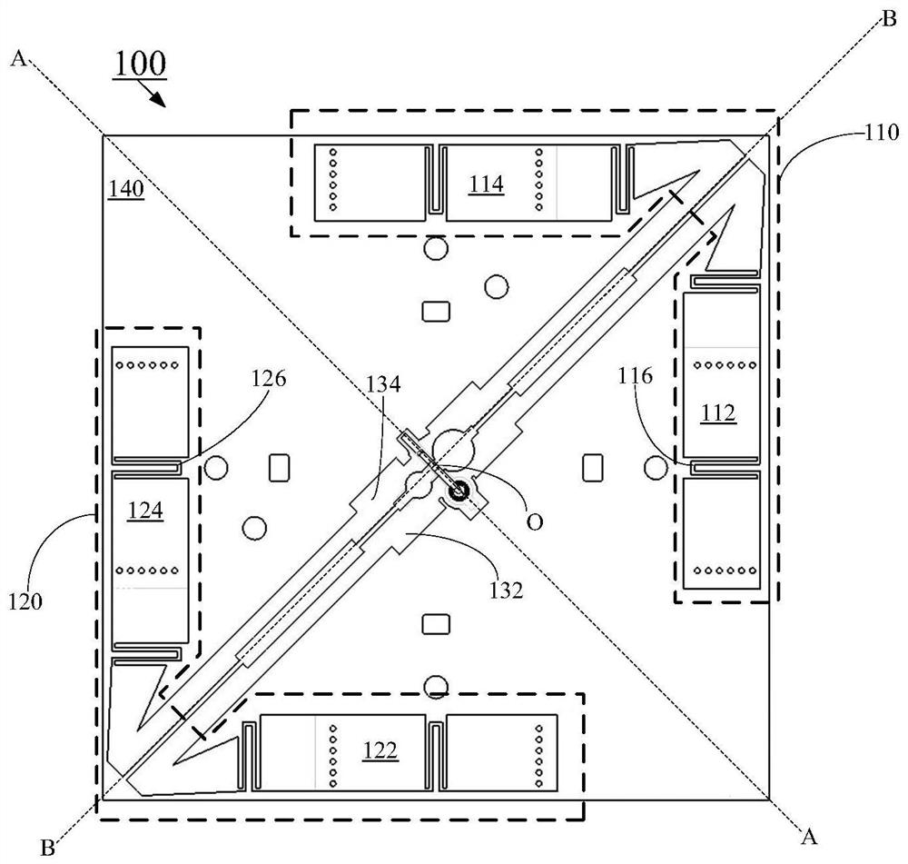
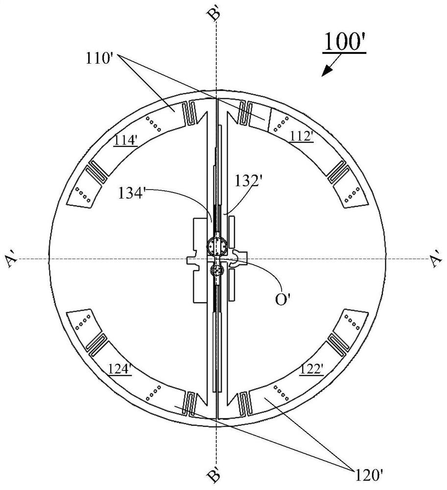
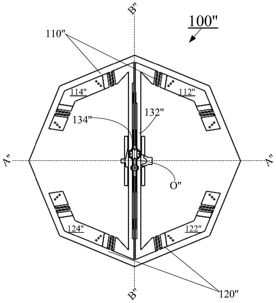
[0037] The advantages and disadvantages of the three traditional forms of radiating elements are described in the background art, but in this disclosure, the inventors innovatively thought of designing the radiating arms of the traditional bowl-shaped radiating element as a planar struct...


PUM


Abstract

The present disclosure relates to a radiating element for an antenna. The radiating element comprises a first pair of dipoles, wherein the first pair of dipoles comprises a first dipole provided with a first radiation arm and a secondradiation arm, and a second dipole provided with a third radiation arm and a fourth radiation arm, a first connecting line between the first radiation arm of the first dipole and the third radiation arm of the second dipole is parallel to a second connecting line between the second radiation arm of the first dipole and the fourth radiation arm of the second dipole, and the radiation arms of the first pair of dipoles are of a planar structure.

Description

technical field [0001] The present disclosure relates to the field of communication, and more particularly relates to a radiating element for an antenna and an antenna including the radiating element. Background technique [0002] In mobile communication, there are three types of radiating elements commonly used in base station antennas, microstrip patch radiating elements, symmetrical dipoles, and bowl-shaped radiating elements fed by four points. [0003] It is difficult to match the microstrip patch radiating element, and its operating bandwidth is narrow, so the microstrip patch radiating element is difficult to meet the broadband requirements of the existing 4G and 4G+ communications. [0004] Symmetrical dipole radiation beams are susceptible to interference and have poor beam stability in the broadband range. [0005] Although the existing four-point fed bowl-shaped radiating element overcomes the above-mentioned shortcomings of the microstrip patch radiating element...

Claims


Application Information

Patent Timeline
IPC IPC(8): H01Q1/36H01Q1/52
CPCH01Q1/36H01Q1/52H01Q1/246H01Q9/16H01Q5/335H01Q9/065
Inventor 杨忠操孙贺
Owner PROSE TECH CO LTD
Features
  • Generate Ideas
  • Intellectual Property
  • Life Sciences
  • Materials
  • Tech Scout
  • Unparalleled Data Quality
  • Higher Quality Content
  • 60% Fewer Hallucinations
Learn More