Solving method of kinematics of underwater mechanical arm based on configuration plane

A technology of underwater machinery and kinematics, used in instruments, adaptive control, control/regulation systems, etc.

Active Publication Date: 2015-10-21
HARBIN ENG UNIV
View PDF5 Cites 13 Cited by
  • Summary
  • Abstract
  • Description
  • Claims
  • Application Information

AI Technical Summary

Problems solved by technology

[0006] The purpose of the present invention is to provide a kind of limitation that overcomes the limitation and the specificity of solving the robot configuration of traditional analysis method, also overcome the g

Method used


Image

  • Solving method of kinematics of underwater mechanical arm based on configuration plane
  • Solving method of kinematics of underwater mechanical arm based on configuration plane
  • Solving method of kinematics of underwater mechanical arm based on configuration plane

Examples


Embodiment 1

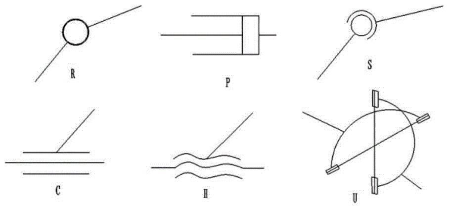
[0151] Implementation 1, combined figure 1 , The space mechanism of the robot is mainly composed of low auxiliary mechanism. The low pair mechanism mainly includes rotating pair (R), moving pair (P), screw pair (H), cylindrical pair (C), plane pair (E), spherical pair (S) and Hooke hinge (HO) or general joint (U). Among them, the degree of freedom of the rotating pair, the moving pair and the screw pair is 1, the degree of freedom of the cylindrical pair (PR) and the universal joint (RR) are 2, and the degree of freedom of the plane pair (PPR) and the spherical pair (RRR) are 3.

Embodiment 2

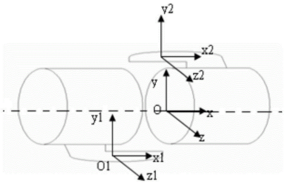
[0152] Implementation 2, combined figure 2 , Modeling of swing module: Establish the coordinate system of the module at the swing center of the module. When the module rotates, the coordinate system of the module is unchanged relative to the connection coordinate system of the previous module, but relative to the connection coordinate system of the next module. The coordinate system changes. Mathematical model matrix of swing module movement:

[0153] T yb = 1 0 0 0 0 cos β yb - sin β yb h yb cos β yb 0 sin β yb cos β yb h yb sin β yb 0 0 0 1 - - - ( 1 )

[0154] Where β yb —The relative angle of rotation of the two parts of the swing module;

[0155] h yb —The length from the center of the swing to the connecting surface of the next module.

Embodiment 3

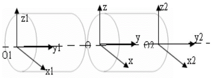
[0156] Implementation 3, combined image 3 , Mobile module modeling: The coordinate system of the module is established on the connecting surface of the fixed part and the moving part of the mobile module. When the module is moved, the coordinate system of the module is unchanged relative to the connection coordinate system of the previous module, and the coordinate system of the next module is unchanged. The coordinate system of the connected module changes relative to the coordinate system of the module. In order to reconstruct the kinematics between the modules, the coordinate matrix on the two connecting surfaces adopts a standard form. The kinematics model of the module is equation (2).

[0157] Movement math model matrix of mobile module:

[0158] T yd = 1 0 0 0 0 1 0 H yd + h yd 0 0 1 0 0 0 0 1 - - - ( 2 )

[0159] Where H yd —The length from the center of the m...


PUM


Abstract

The invention provides a solving method of kinematics of an underwater mechanical arm based on a configuration plane. The calculation method comprises steps of inputting joint parameters of the underwater mechanical arm by carrying out analysis for mechanical arm joints, resolving the known working configuration of a robot according to types of joint modules, resolving the robot joints into corresponding types of basic joints according to movement types and inputting position arrays of target points of the robot; and modeling the basic joints by carrying out kinematical modeling for basic moving joints forming the space mechanical arm, and normalizing the kinematical modeling to form a unified modeling method. According to the invention, disadvantages are solved that solving is complex and it is hard to remove incorrect solution from multiple solutions in a traditional analytic method; problems of poor real-time performance and low precision of the common iteration method are solved; solving for inverse kinematics of the robot can be quickly and precisely achieved; and actual application requirements of the underwater mechanical arm are met.

Description

Technical field [0001] The invention provides a method for solving the kinematics of an underwater manipulator based on a configuration plane. Background technique [0002] With the wide application of industrial robot technology, the application of space 6R tandem mechanism has important significance. The inverse kinematics solution of the tandem mechanism is a prerequisite for the control calculation of the tandem robot. It is directly related to the offline programming, trajectory planning, and real-time control of the robot. It occupies an important position in robotics. Only the inverse kinematics solution can transform the spatial pose It is the joint variable to realize the programming control of the robot end effector according to the spatial pose (such as linear trajectory and arc trajectory, etc.). [0003] In the kinematics of the series mechanism, the inverse kinematics solution of the space 6R series mechanism is the most difficult. This problem is the same as the inv...

Claims


Application Information

Patent Timeline
IPC IPC(8): G05B13/04
Inventor 魏延辉王泽鹏杨子扬于媛媛刘合伟周星和胡加兴贾献强高苇杭
Owner HARBIN ENG UNIV
Why Eureka
Try Eureka