Device and Method for Fluidic Coupling of Fluidic Conduits to a Microfludic Chip, and Uncoupling Thereof

a fluidic conduit and microfluidic chip technology, applied in the direction of metal-working holders, large fixed members, supporters, etc., can solve the problem that state-based solutions at least partially do not meet the requirements, and achieve the effect of sufficient precision

Inactive Publication Date: 2010-12-23
MICRONIT MICROTECHNOLOGIES BV
View PDF16 Cites 13 Cited by
  • Summary
  • Abstract
  • Description
  • Claims
  • Application Information

AI Technical Summary

Benefits of technology

[0012]Aligning means, preferably spring-mounted aligning members, preferably balls, and recesses co-acting therewith are preferably provided for the mutual alignment of the outer ends of the fluidic conduits and the microfluidic chip. ‘Aligning members’, ‘balls’ and ‘recesses’ can be understood here and in the following to also mean respectively ‘aligning member’, ‘ball’ and ‘recess’, although generally there will be a plurality of aligning members, balls and recesses. The microfluidic chip and the outer ends of the fluidic conduits can thus be aligned with each other in sufficiently precise manner.
[0013]For the purpose of sealing a connection of a fluidic conduit to the microfluidic chip, use is preferably made here of a conical receiving space which is provided for this purpose and in which a sealing member with a corresponding conical outer surface is at least partially received, wherein the sealing member is urged into the conical receiving space by means of second urging means provided for this purpose, preferably a spring. A resilient seal also has the advantage that expansion and contraction, for instance due to thermal loads, can be compensated. Use can be made here of a sealing auxiliary means in which the conical receiving space is arranged. The second urging means are preferably biased. It thus becomes possible to urge the sealing member with a greater force into the conical receiving space. This and other aspects relating to the invention will be further elucidated in the following more detailed description of exemplary embodiments of the invention.

Problems solved by technology

All the stated solutions at least partially do not meet the requirements which can be set in respect of convenience of use, speed of operation, temperature resistance, sealing, chemical resistance, reproducibility and so forth.

Method used


Image

  • Device and Method for Fluidic Coupling of Fluidic Conduits to a Microfludic Chip, and Uncoupling Thereof
  • Device and Method for Fluidic Coupling of Fluidic Conduits to a Microfludic Chip, and Uncoupling Thereof
  • Device and Method for Fluidic Coupling of Fluidic Conduits to a Microfludic Chip, and Uncoupling Thereof

Examples


Embodiment Construction

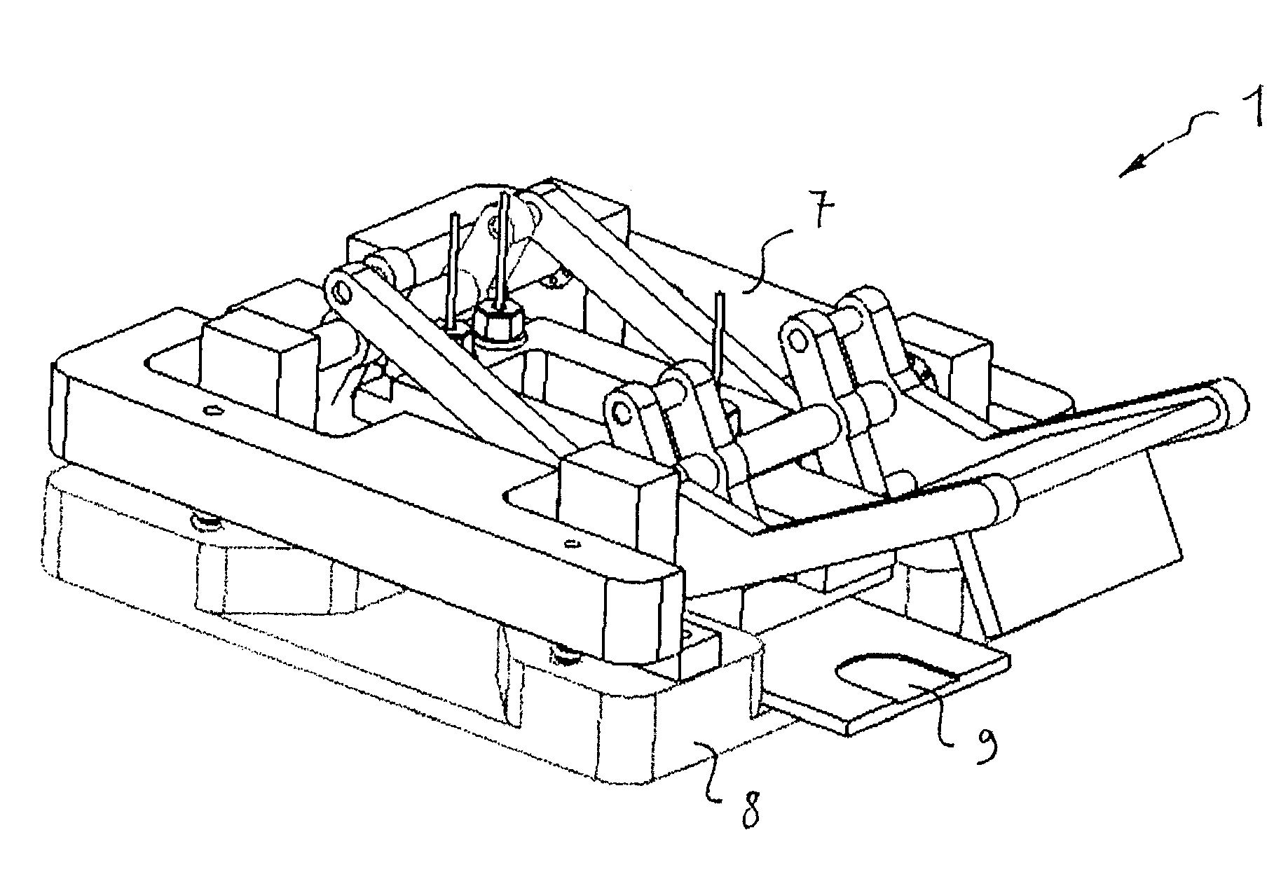
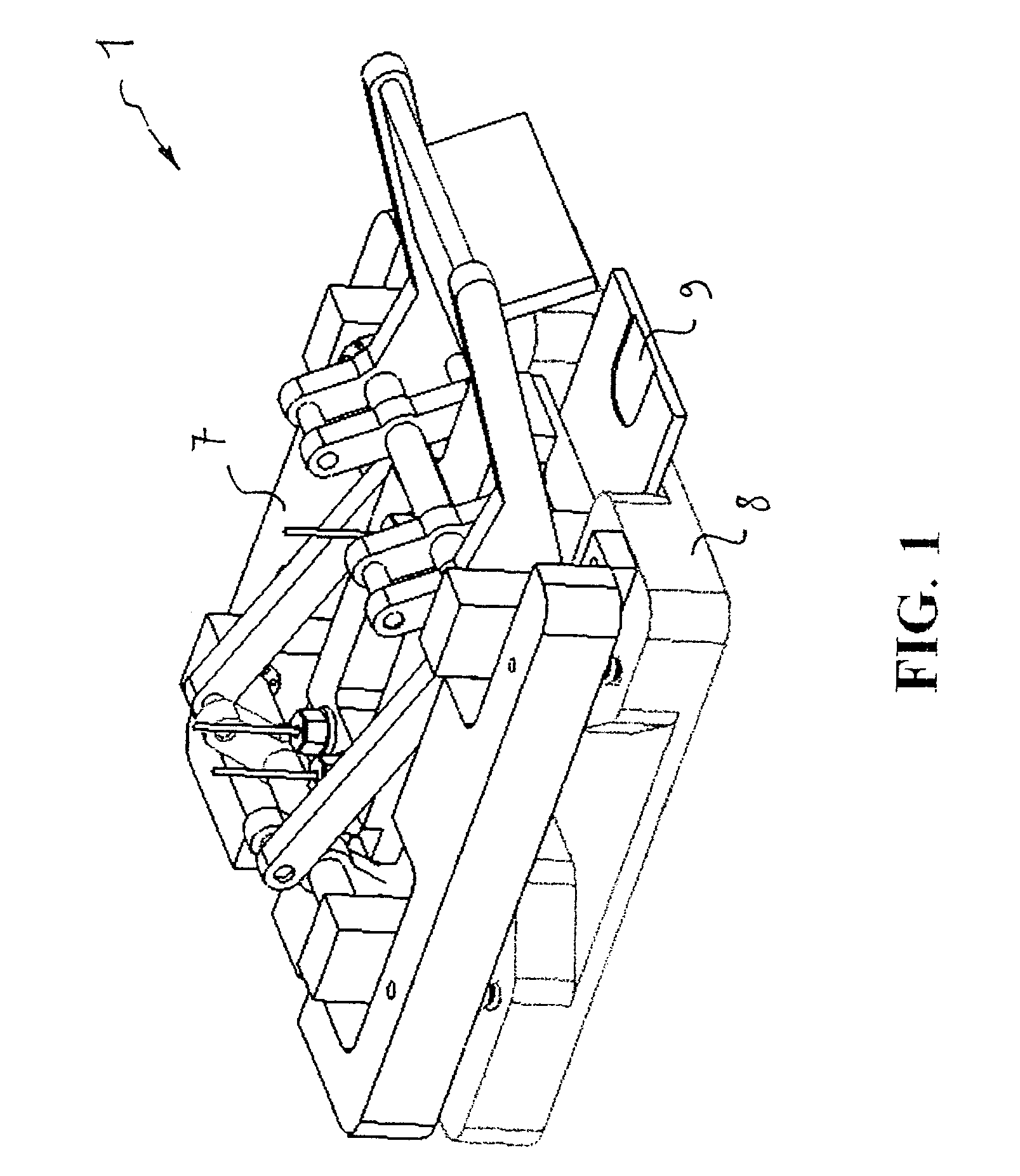
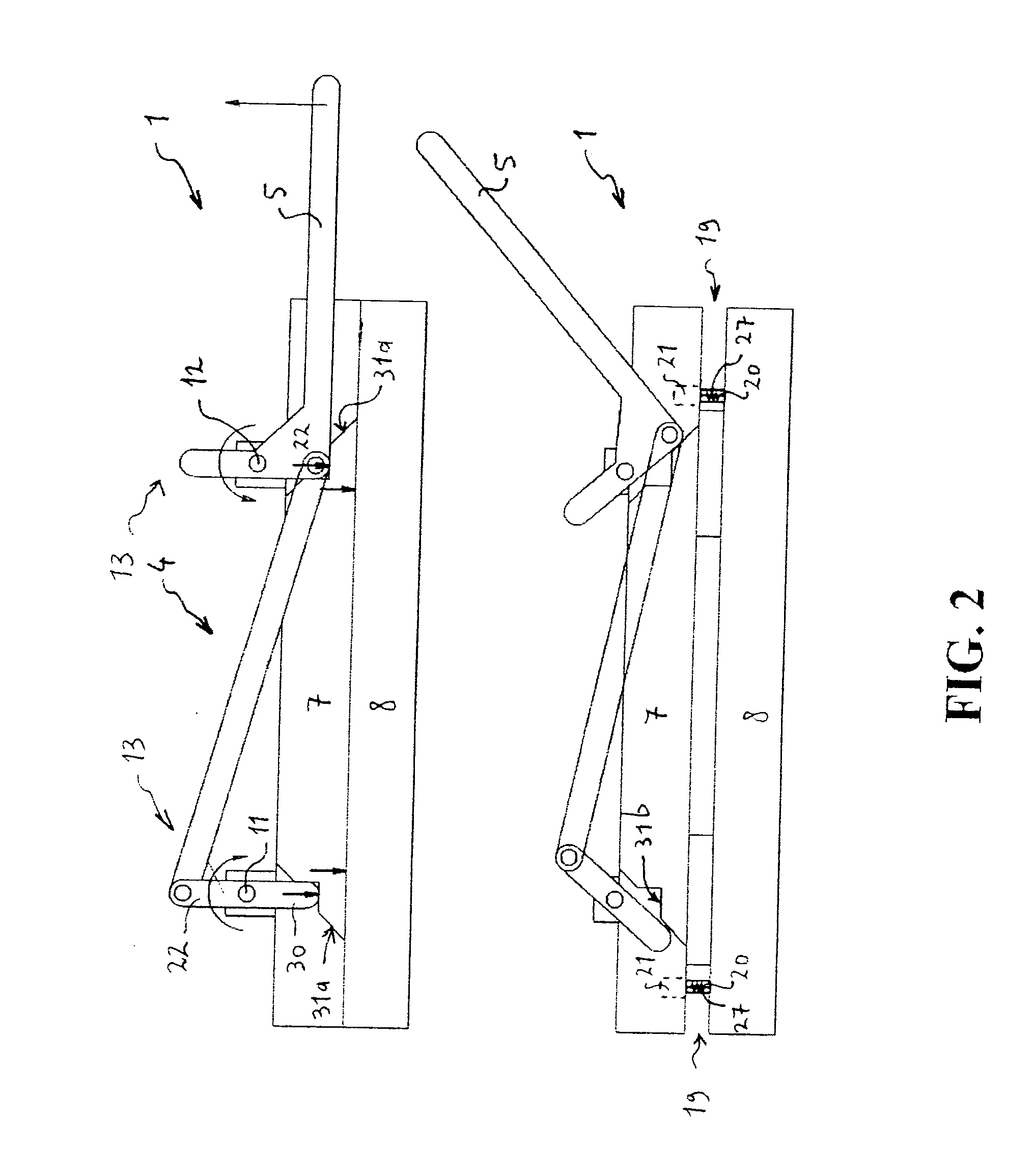
[0019]A preferred embodiment of a device (1) according to the invention comprises a first structural part (7) and a second structural part (8) and also a mechanism (4) for mutually perpendicular movement toward and away from each other of first structural part (7) and second structural part (8). Mechanism (4) comprises for this purpose a dual lever mechanism (13) with two shafts (11,12) rotating in opposite directions which are provided with mutually coupled cranks (22) and can be operated by means of a single handle (5). Guide means (19) in the form of cylindrical guides (20) and recesses (21) co-acting therewith provide for guiding of the relative movement of first structural part (7) and second structural part (8). First structural part (7) and second structural part (8) are urged apart by means of urging means in the form of springs (27). Second structural part (8) comprises a removable part (9) with a receiving space (14) for receiving a microfluidic chip (3). Removable part (9...


PUM

PropertyMeasurementUnit
temperaturesaaaaaaaaaa
pressuresaaaaaaaaaa
transmission ratioaaaaaaaaaa

Abstract

A system for fluidic coupling and uncoupling of fluidic conduits and a microfluidic chip, wherein the fluidic conduits are connected mechanically to a first structural part and the microfluidic chip is carried by a second structural part. The structural parts are moved perpendicularly toward and away from each other by means of a mechanism provided for this purpose. Outer ends of the fluidic conduits can thus be moved over a determined distance substantially perpendicularly to the outer surface of the microfluidic chip and connecting openings in the outer surface of the microfluidic chip. This enables accurate realization of fluidic coupling and uncoupling without the occurrence of undesirable moments of force and with minimal risk of damage to the fluidic conduits or the connecting openings. With such system requirements which can be set in respect of convenience, speed, temperature resistance, sealing, chemical resistance, reproducibility and so forth, can be fulfilled.

Description

FIELD OF THE INVENTION[0001]The invention relates to a device for fluidic coupling of fluidic conduits to a microfluidic chip, and uncoupling thereof, which device comprises a first structural part to which the fluidic conduits can be mechanically coupled and a second structural part which can carry the microfluidic chip. The invention also relates to a method for fluidic coupling of fluidic conduits to a microfluidic chip, and uncoupling thereof, which method comprises of:[0002]mechanically coupling the fluidic conduits to a first structural part; and[0003]having the microfluidic chip carried by a second structural part.BACKGROUND OF THE INVENTION[0004]Microfluidics is concerned with microstructural devices and systems with fluidic functions. This may relate to the manipulation of very small quantities of liquid or gas in the order of microlitres, nanolitres or even picolitres. Important applications lie in the field of biotechnology, chemical analysis, medical testing, process mon...

Claims


Application Information

Patent Timeline
Patent Type & Authority Applications(United States)
IPC IPC(8): F16L55/00B23P19/02
CPCB01L3/502715Y10T29/53678B01L9/527B01L2200/025B01L2200/027B01L2300/0816Y10T29/49945Y10T29/53983Y10T29/53709Y10T29/53943Y10T29/53996Y10T29/53987Y10T29/53783Y10T29/5367B01L3/565
Inventor VAN'T OEVER, RONNYBLOM, MARKO THEODOORBUESINK, WILFRED
Owner MICRONIT MICROTECHNOLOGIES BV
Why Eureka
Try Eureka