
Maximum torque current ratio control method and device

A technology of maximum torque current and control method, applied in the direction of control of electromechanical transmission, motor generator control, AC motor control, etc., can solve problems such as unprovided solutions, accuracy requirements of speed sensors, and difficulty in directly measuring motors, etc. Achieve the effect of avoiding torque ripple, improving operating efficiency and reducing dependence

Pending Publication Date: 2021-05-28
GREE ELECTRIC APPLIANCES INC
View PDF6 Cites 6 Cited by
  • Summary
  • Abstract
  • Description
  • Claims
  • Application Information

AI Technical Summary

Problems solved by technology

[0003] In related technologies, since it is difficult to directly measure the torque of the motor in practical applications, the torque can only be replaced by measuring the rotational speed. However, this algorithm has high requirements on the accuracy of the speed sensor
[0004] Aiming at many technical problems existing in related technologies, effective solutions have not yet been provided

Method used


Image

  • Maximum torque current ratio control method and device
  • Maximum torque current ratio control method and device
  • Maximum torque current ratio control method and device

Examples


Embodiment Construction

[0060] In order to make the purposes, technical solutions and advantages of the embodiments of the present application clearer, the technical solutions in the embodiments of the present application will be clearly and completely described below in conjunction with the drawings in the embodiments of the present application. Obviously, the described embodiments It is a part of the embodiments of this application, but not all of them. Based on the embodiments in the present application, all other embodiments obtained by persons of ordinary skill in the art without making creative efforts belong to the protection scope of the present application.

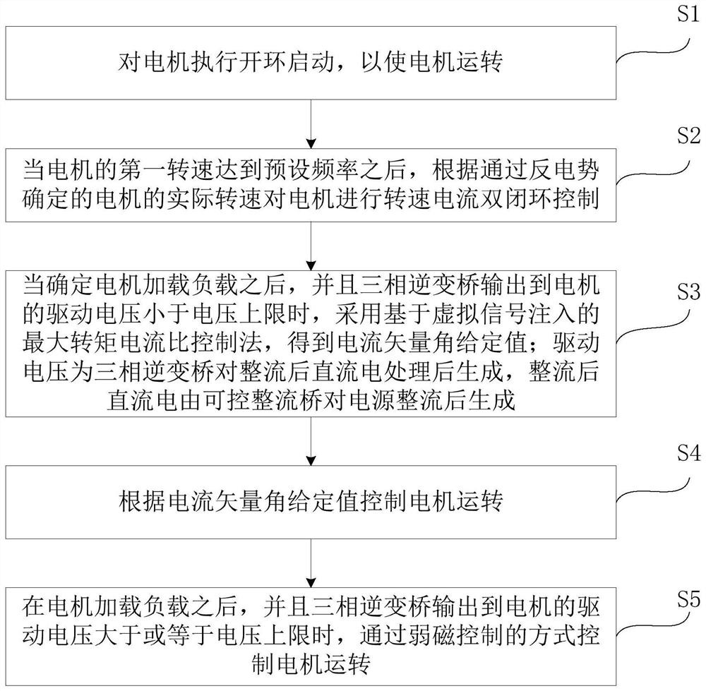
[0061] figure 1 A maximum torque-to-current ratio control method provided in the embodiment of the present application includes steps S1 to S4 as follows:

[0062] Step S1, performing an open-loop start on the motor to make the motor run.

[0063] Specifically, open-loop starting may be a method of injecting voltage or current into th...


PUM


Abstract

The invention relates to a maximum torque current ratio control method and device. The method comprises the steps: carrying out open-loop starting on a motor so as to enable the motor to operate; after the first rotating speed of the motor reaches a preset frequency, carrying out rotating speed and current double-closed-loop control on the motor according to the actual rotating speed, determined through counter electromotive force, of the motor; when it is determined that a load is loaded on the motor and a driving voltage output to the motor by a three-phase inverter bridge is smaller than a voltage upper limit, adopting a maximum torque current ratio control method based on virtual signal injection to obtain a current vector angle given value; and controlling the motor to operate according to the current vector angle given value. According to the method provided by the embodiment of the invention, the dependence on the parameters of a permanent magnet synchronous motor is reduced in an implementation process while the defects of torque ripple, high-frequency noise, additional loss and the like existing in a traditional high-frequency signal injection method are effectively avoided; and requirements in the aspects of real-time calculation complexity, dynamic response performance, stability and the like in control are comprehensively considered while the operation efficiency of the permanent magnet synchronous motor is improved.

Description

technical field [0001] The present application relates to the technical field of permanent magnet synchronous motor control, in particular to a maximum torque-to-current ratio control method and device. Background technique [0002] The built-in permanent magnet synchronous motor (IPMSM for short) has excellent characteristics such as small size, high efficiency, and high power factor, and has been widely used this year. In order to realize the efficient control of IPMSM, the maximum torque current ratio (abbreviated as MTPA) control strategy is often adopted. The maximum torque-to-current ratio control strategy is a control method that can output greater torque under the same current. This control strategy is realized by setting the appropriate d-axis (direct axis) current given value, q-axis (quadrature axis) ) current given value, so that under the same output torque, the stator current amplitude reaches the minimum. The advantage of this method is that, on the one hand...

Claims


Application Information

Patent Timeline
Patent Type & Authority Applications(China)
IPC IPC(8): H02P21/00H02P21/14H02P21/13H02P21/18H02P21/22H02P21/24H02P21/30H02P27/12H02M5/458
CPCH02P21/0003H02P21/14H02P21/13H02P21/18H02P21/22H02P21/24H02P21/30H02P27/12H02M5/4585
Inventor 赵文超张统世黄强许柳
Owner GREE ELECTRIC APPLIANCES INC
Learn More