Motor rotor position full-automatic calibration system and calibration method

A technology for calibrating systems and motor rotors, applied in control systems, generator control, motor control, etc., can solve the problems that manual calibration is not suitable for large-scale batch production, efficiency and consistency cannot be guaranteed, and is restricted by the site.

Active Publication Date: 2021-05-28
SHENZHEN BOYONG TECH
View PDF4 Cites 0 Cited by
  • Summary
  • Abstract
  • Description
  • Claims
  • Application Information

AI Technical Summary

Problems solved by technology

There are obvious defects in this manual calibration process. On the one hand, the calibration accuracy is heavily dependent on the precision of machining and measuring tools. On t

Method used


Image

  • Motor rotor position full-automatic calibration system and calibration method
  • Motor rotor position full-automatic calibration system and calibration method
  • Motor rotor position full-automatic calibration system and calibration method

Examples


Embodiment Construction

[0026] The present invention will be further described below in conjunction with the accompanying drawings and specific embodiments. Terms such as "upper", "lower", "left", "right", "middle" and "one" quoted in the preferred embodiment are only for convenience of description, and are not used to limit the scope of the present invention. The scope of implementation and the change or adjustment of its relative relationship shall also be regarded as the scope of implementation of the present invention without substantive changes in technical content.

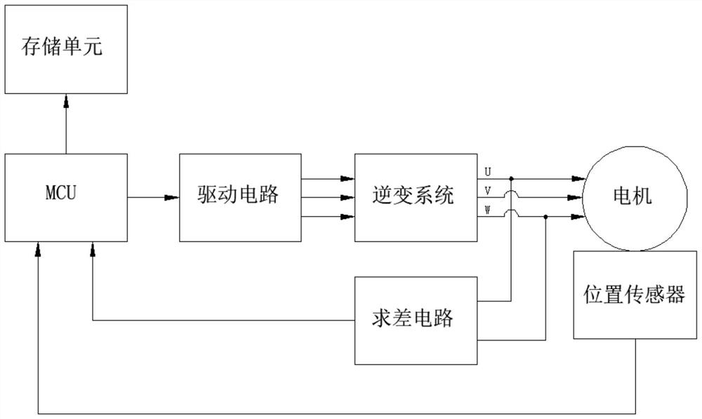
[0027] Such as figure 1 As shown, the fully automatic calibration system for the motor rotor position includes a motor, a difference seeking circuit, a position sensor, an MCU, and a storage unit; the difference seeking circuit is connected to any two of the three phase lines U, V, and W of the motor for Sampling the back electromotive force of the two phase lines connected to the motor running in the power generation state and pe...


PUM


Abstract

The invention discloses a motor rotor position full-automatic calibration system and calibration method, and the system comprises a motor, a differencing circuit, aposition sensor and a MCU; the differencing circuit is connected with any two phase lines of the U, V and W phase lines of the motor, and is used for sampling back electromotive forces on the two phase lines connected with the differencing circuit when the motor runs in a power generation state and carrying out differencing operation; the position sensor is concentrically fixed with the rotating shaft of the motor, detects the angle of the rotating shaft of the motor in real time and outputs a corresponding detection signal; and the MCU is connected with the U, V and W phase lines of the motor through the driving circuit so as to control the motor to run, and is also connected with the differencing circuit and the position sensor so as to obtain a result signal and a detection signal of differencing operation in real time, and calibration is carried out according to the result of differencing operation and the detection signal. According to the invention, full-automatic calibration is realized, manual intervention can be avoided in the calibration process, and the matching process of the motor rotor position and the position sensor is automatically completed.

Description

technical field [0001] The invention relates to the technical field of motor control, in particular to a fully automatic calibration system and calibration method for the position of a motor rotor. Background technique [0002] In the field of motor applications, especially where the requirements for load capacity and control accuracy are relatively high, the position sensor is a key component. It can provide the precise position of the motor rotor at various speeds, so that the motor controller has high-precision, high-efficiency and fast-response motor control capabilities. [0003] There are many types of motor position sensors, including resolvers, magnetic encoders, Hall switches, and more. The common disadvantage in their use is that manual mechanical zero adjustment is required during installation, that is, by manually adjusting the installation position or angle of the sensor to match the zero point of the magnetic field of the motor, so as to match the output angle...

Claims


Application Information

Patent Timeline
IPC IPC(8): H02P21/18H02P21/32
CPCH02P21/18H02P21/32H02P2203/03
Inventor 项春亮朱子宇王冬亮石文光
Owner SHENZHEN BOYONG TECH
Why Eureka
Try Eureka