Shifting fork and shifting fork shaft of additional power output device of mini-tiller

A technology of power output and shifting fork shaft is applied in the field of micro-tillers, which can solve the problems of cumbersome installation and disassembly process, inconvenient use, etc., and achieve the effects of simple structure, reduced labor, and improved efficiency.

Inactive Publication Date: 2021-06-01
姜建中
View PDF0 Cites 0 Cited by
  • Summary
  • Abstract
  • Description
  • Claims
  • Application Information

AI Technical Summary

Problems solved by technology

Its installation and disassembly process is cumbersome and troublesome, which brings inconvenience to users

Method used


Image

  • Shifting fork and shifting fork shaft of additional power output device of mini-tiller
  • Shifting fork and shifting fork shaft of additional power output device of mini-tiller
  • Shifting fork and shifting fork shaft of additional power output device of mini-tiller

Examples


Embodiment Construction

[0028] The embodiments of the present invention will be described in detail in conjunction with the accompanying drawings.

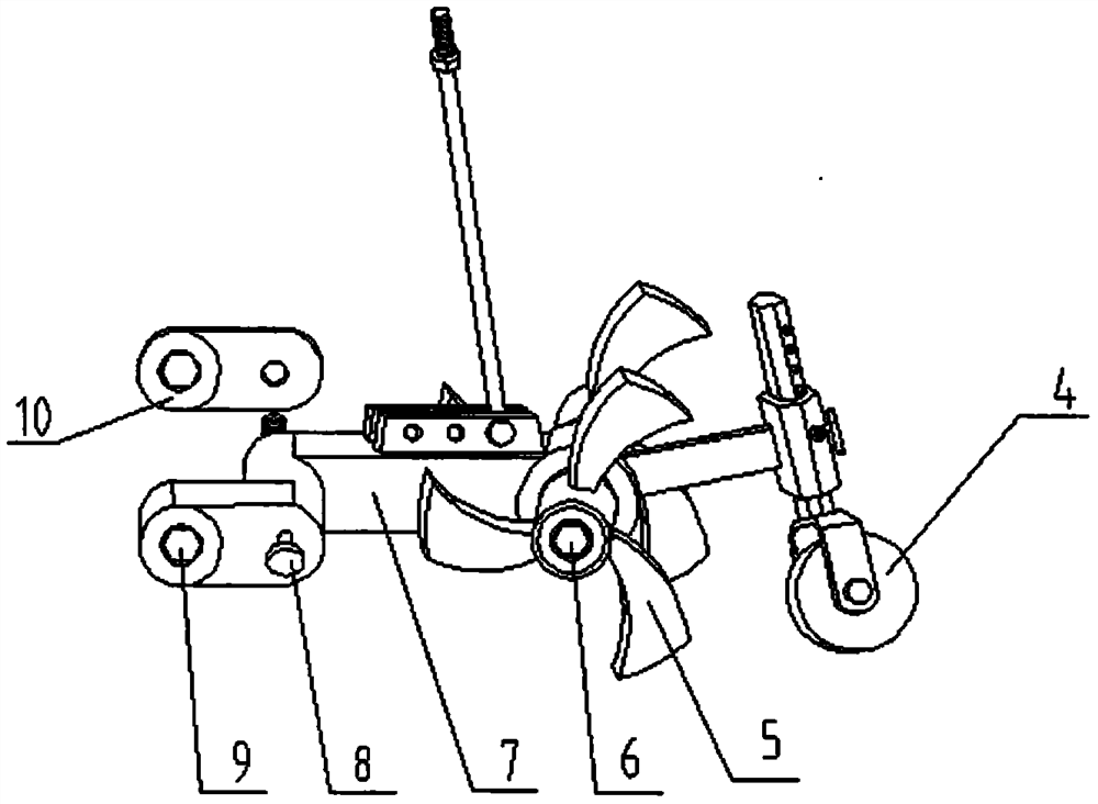
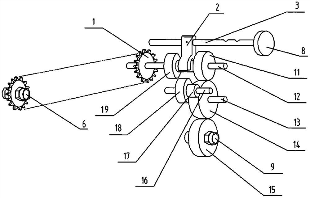
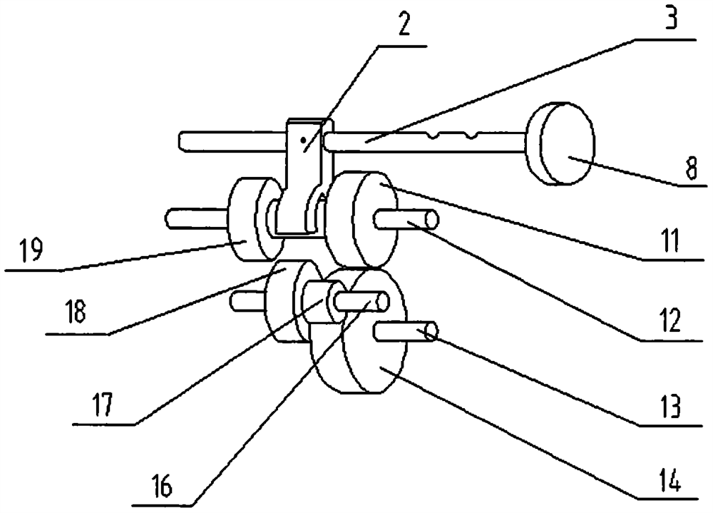
[0029] Such as figure 1 , figure 2 , image 3 and Figure 4 As shown, the structure of the present invention includes: the casing of the micro tillage machine's additional power output device, a shift fork, a shift fork shaft, a handle, a groove, and a double spur gear. Wherein, the double spur gear and the main shaft are slidably connected by splines, and the middle position of the double spur gear is provided with a shift fork slot, and the shift fork is fixed on the shift fork shaft in the box, and the shift fork extends into the double Inside the shift fork slot of the spur gear. There is a positioning groove on the shift fork shaft, and a spring touch ball is arranged on the box body. The shift fork shaft is installed on the box body through clearance fit, and a handle is installed at one end of the shift fork shaft extending out of the box bo...


PUM


Abstract

The invention discloses a shifting fork and shifting fork shaft of an additional power output device of a mini-tiller. The shifting fork and the shifting fork shaft comprise a shifting fork body, a shifting fork shaft body, a control device and a positioning device. A variable-speed gear-shifting component on the additional power output device of the mini-tiller which locally rotates up and down can be effectively controlled. The power output shaft can output variable-speed and variable-direction power. The shifting fork and the shifting fork shaft are provided for operation of a ditching cutter and a rotary tillage cutter, and can meet the tillage requirement of a user. The structure is simple, and the maintenance is convenient. The labor amount of operators is reduced, the time is saved, and the operation efficiency is improved.

Description

【Technical field】 [0001] The invention relates to the technical field of tillage machines, in particular to a shift fork and a shift fork shaft of an additional power output device of a tiller. 【Background technique】 [0002] In order to adapt the micro tillage machine to multi-functional work, we socket the micro tillage machine's additional power output device and implements on the power output shaft of the travel box of the micro tiller. The tiller drives the implements on the power output shaft of the walking box and the implements on the additional power output device of the tiller to rotate at the same time, forming a double implement operation and expanding the application range of the tiller. The implements include: traveling wheels, rotary cultivating knives and ditching knives. [0003] The power output shaft of the walking box of the tiller is socketed with the traveling wheel and the power input shaft of the additional power output device of the tiller, and the ...

Claims


Application Information

Patent Timeline
IPC IPC(8): A01B33/08
CPCA01B33/082
Inventor 姜建中
Owner 姜建中
Why Eureka
Try Eureka