Lawn transplanting and cutting machine with secondary cutting function
A secondary cutting and cutting machine technology, applied in lawn growth, plant cultivation, botanical equipment and methods, etc., can solve the problems of long time consumption and low cutting efficiency, and achieve the effect of speeding up cutting efficiency
- Summary
- Abstract
- Description
- Claims
- Application Information
AI Technical Summary
Problems solved by technology
Method used
Image

Examples
Embodiment 1
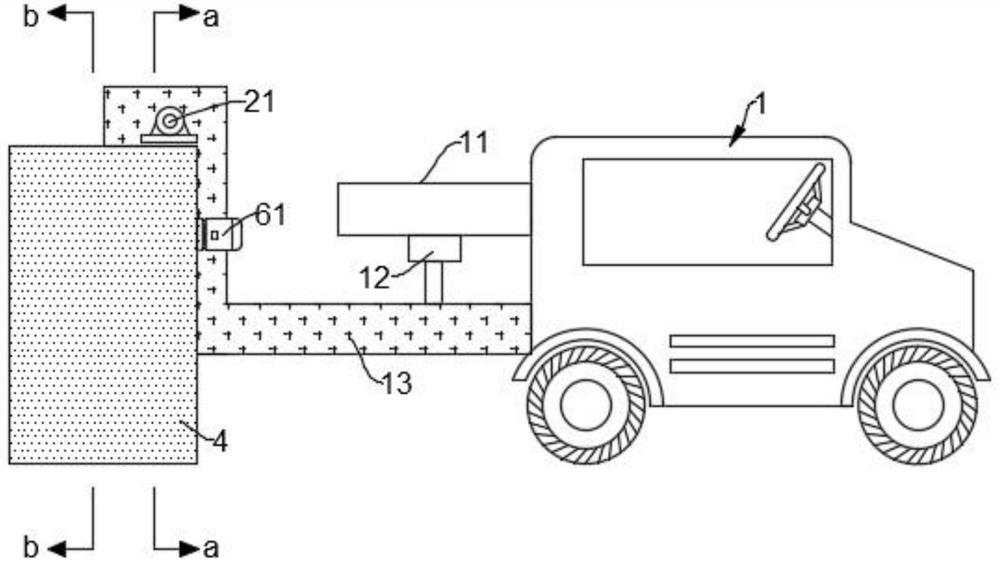
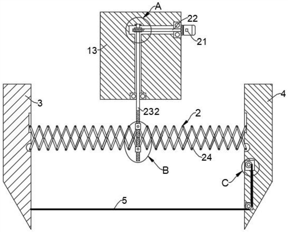
[0032] Such as Figure 1-7 As shown, a lawn transplanting and cutting machine for secondary cutting includes a fixed plate 11 fixedly connected to the vehicle body 1, and the bottom end of the fixed plate 11 is connected with a fixed block 13 through a hydraulic cylinder 12, and the fixed block 13 is provided with an adjustment mechanism 2 , the adjusting mechanism 2 is respectively connected with a first limiting plate 3 and a second limiting plate 4 .
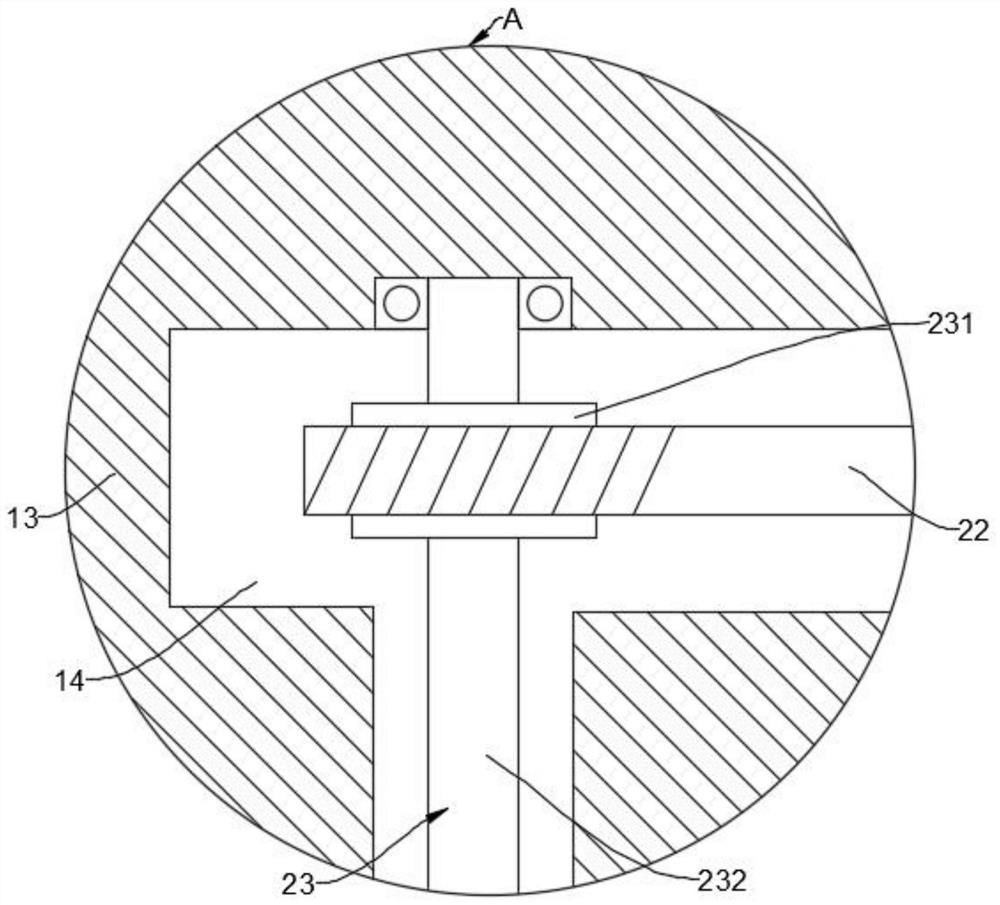
[0033] The adjustment mechanism 2 is composed of a first motor 21, a drive shaft 22, a worm assembly 23 and a telescopic link 24. The first motor 21 is fixedly connected to the outer wall of the fixed block 13, and the output end of the first motor 21 is fixedly connected to the drive shaft 22. The drive shaft 22 is rotatably connected with the fixed block 13 , and the fixed block 13 is provided with a transmission cavity 14 . The end of the drive shaft 22 away from the first motor 21 is connected with the middle part of the ...
Embodiment 2
[0049] Such as Figure 8 As shown, the difference between this embodiment and Embodiment 1 is that an adjustment chamber 31 is provided in the first limiting plate 3, a sliding block 32 is slidably connected to the adjustment chamber 31, and a tension spring 33 is fixedly connected to the top of the sliding block 32. , the top end of the tension spring 33 is fixedly connected with the adjustment chamber 31 , and the bottom end of the sliding block 32 is fixedly connected with the cutting rope 5 .
[0050] After the first limiting plate 3 and the second limiting plate 4 positions are fixed, the rotation of the take-up wheel 63 will make the sliding block 32 be pulled down, and the sliding block 32 will be in contact with the bottom wall of the adjustment chamber 31 Compensating for the setting, in the actual process, the tension spring 33 can keep the cutting rope 5 with a strong tension all the time, thereby ensuring that the cutting rope 5 always has a good cutting effect on ...
Embodiment 3
[0052] Such as Figure 9-10 As shown, the difference between this embodiment and Embodiment 1 is that a reciprocating cavity 34 is provided in the first limiting plate 3, and a horizontal shaft 35 is rotatably connected to the reciprocating cavity 34, and one side of the first limiting plate 3 is fixedly connected There is a fourth motor 36, the output end of the fourth motor 36 is fixedly connected to the horizontal shaft 35, the horizontal shaft 35 is located in the reciprocating chamber 34 and is fixedly connected to a turntable 37, and the eccentric part of the turntable 37 away from the horizontal shaft 35 is rotatably connected to a connecting column 38 , the connecting column 38 is fixedly connected with the cutting rope 5 .
[0053] A spring 64 is arranged between the take-up wheel 63 and the connecting shaft 62 , and the take-up wheel 63 is connected with the connecting shaft 62 through the spring 64 .
[0054] When the fourth motor 36 works, the fourth motor 36 will...
PUM
 Abstract
Description
Claims
Application Information
 - R&D
- Intellectual Property
- Life Sciences
- Materials
- Tech Scout
- Unparalleled Data Quality
- Higher Quality Content
- 60% Fewer Hallucinations
Browse by: Latest US Patents, China's latest patents, Technical Efficacy Thesaurus, Application Domain, Technology Topic, Popular Technical Reports.
© 2025 PatSnap. All rights reserved.Legal|Privacy policy|Modern Slavery Act Transparency Statement|Sitemap|About US| Contact US: help@patsnap.com