Automatic feed feeding machine for livestock breeding

A technology of automatic feeding and feeding, applied in animal husbandry, application, poultry industry, etc., can solve the problems of raising the cost of breeding, affecting the appetite of livestock, affecting the next consumption, etc., so as to reduce the amount of labor used and the intensity of labor. , the effect of reducing the amount of waste

Inactive Publication Date: 2021-06-01
钟离平
View PDF0 Cites 0 Cited by
  • Summary
  • Abstract
  • Description
  • Claims
  • Application Information

AI Technical Summary

Problems solved by technology

[0003] In animal husbandry, the size of the breeding scale determines the benefits of breeding. In some large-scale breeding factories, large-scale livestock and poultry are often raised. Therefore, how to raise such livestock and poultry has become the key to animal husbandry; in the process of animal husbandry It is necessary to add the feed in the breeding shed regularly and quantitatively. When there are many livestock, it is necessary to invest a lot of manpower to stir and distribute the feed and add it to the feed trough. However, if the feed is put into the feed trough at one time, sometimes The livestock can't finish eating, the remaining feed not only affects the appetite of the livestock, but also the excess feed will affect the next consumption under the activity of the livestock, which will greatly increase the breeding cost and have a certain impact on the growth of the livestock. Therefore, the present invention proposes a Automatic Feed Feeder for Breeding Animal Husbandry

Method used


Image

  • Automatic feed feeding machine for livestock breeding
  • Automatic feed feeding machine for livestock breeding
  • Automatic feed feeding machine for livestock breeding

Examples


Embodiment 1

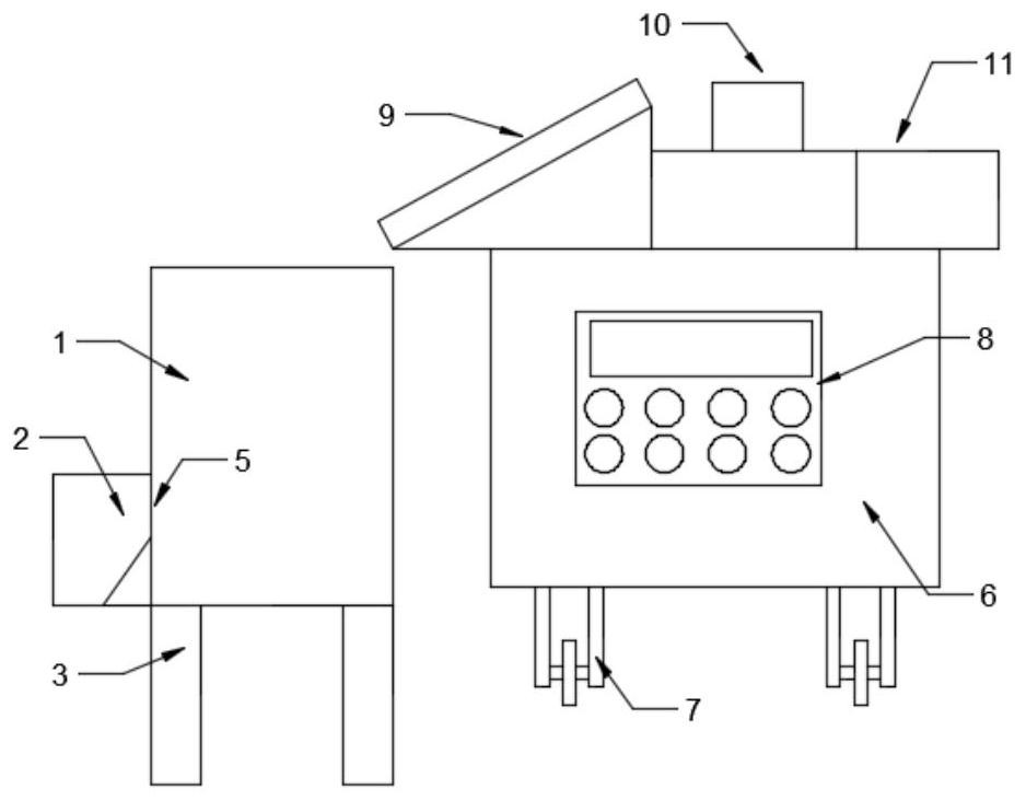
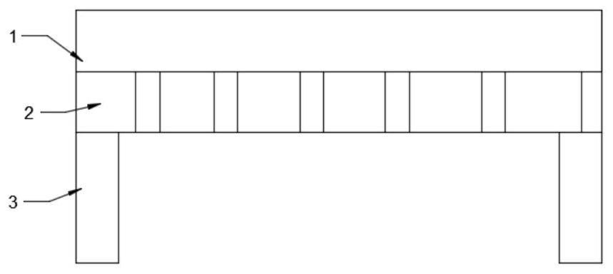
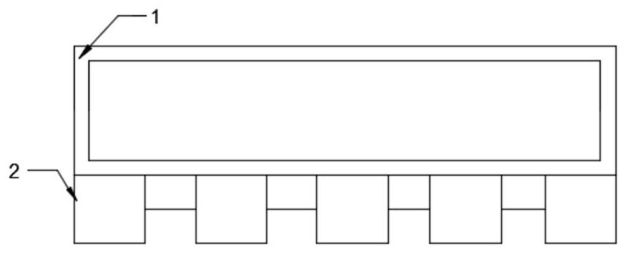
[0032] see Figure 1-12 , in the embodiment of the present invention, an automatic feed feeder for animal husbandry, comprising: a trough 1, a food box 2 is fixed on one side of the trough 1, and a leg 3 is fixed on the bottom of the trough 1, so that The trough body of the hopper 1 on one side of the food box 2 is provided with a feed opening 4, and a baffle mechanism 5 is fixedly installed on the feed chute 1 on the feed opening 4, and the other side of the feed trough 1 is provided with There is a mobile box 6, the bottom of the mobile box 6 is equipped with universal wheels 7, the casing of the mobile box 6 is provided with a control panel 8, and the top of the mobile box 6 is fixedly equipped with an unloading mechanism 9. A transfer mechanism 10 is fixedly installed on one side of the feed mechanism 9, and a feed stirring mechanism 11 is fixed on the top of the moving box 6 on the other side of the transfer mechanism 10.

Embodiment 2

[0034] see Figure 1-12, in this embodiment, the baffle plate mechanism 5 includes: a guide rail 501 fixedly installed on the trough 1 on both sides of the feed opening 4, a baffle plate 502 is slidably installed in the guide rail 501, the The upper part of the baffle plate 502 is rotatably connected with a first connecting rod 503, the other end of the first connecting rod 503 is rotatably connected with a crutch 504, and the middle part of the crutch 504 is rotatably connected with a first rocker 505, and the first rocker The end of 505 is provided with a first rotating pin 506, and the first rotating pin 506 is fixedly installed on the tank body of the trough 1, and the other end of the turning rod 504 is connected with a first crank 507 in rotation, and the first crank 507 A first rotating rod 508 is fixedly installed at the end.

[0035] In this embodiment, the size of the baffle 502 is larger than that of the feeding opening 4, and the baffle 502 is used to block the fe...

Embodiment 3

[0037] see Figure 1-12 , in this embodiment, the dumping mechanism 9 includes: a base 901, a first rotating base 902 is fixed on one side of the upper part of the base 901, and a first pole 903 is rotatably mounted on the first rotating base 902, so The middle part of the first pole 903 is provided with a second pivot pin 913, and the second pole 907 is rotated on the second pivot pin 913 at the same time, and the top of the first pole 903 and the second pole 907 are fixedly installed. There is a flat plate 908; the other side of the base 901 is fixed with a slot plate 904, and the slot plate 904 is provided with a chute 905, and a round rod 906 is slidably installed in the chute 905, and the two ends of the round rod 906 It is rotatably connected with the second pole 907, and a rolling bar 909 is rotatably installed inside the base 901, and a rotating connecting block 910 is arranged in the middle of the rolling bar 909, and a hydraulic press 911 is fixedly installed on one ...


PUM


Abstract

The invention relates to the related technical field of livestock breeding equipment, in particular to an automatic feed feeding machine for livestock breeding. The automatic feed feeding machine comprises a feed trough; a feed box is fixed on one side of the feed trough; support legs are fixed at the bottom of the feed trough; a feed passing port is formed in a trough body of the feed trough on one side of the feed box; a baffle mechanism is fixedly mounted on the feed trough on the feed passing port; a movable box is arranged on the other side of the feed trough; universal wheels are installed at the bottom of the movable box; a control panel is arranged on a box body of the movable box; a material pouring mechanism is fixedly installed on the top of the movable box; a transferring mechanism is fixedly installed on one side of the material pouring mechanism; and a feed stirring mechanism is fixed to the position, on the other side of the transferring mechanism, of the top of the movable box. According to the device, mechanical automatic operation is utilized, stirring processing and timed and quantitative adding of feed are achieved, the labor intensity of workers is reduced, the use amount of the workers is reduced, and meanwhile, the waste use amount of the feed is reduced, and the breeding benefits are greatly improved.

Description

technical field [0001] The invention relates to the related technical field of animal husbandry equipment, in particular to an automatic feed feeding machine for animal husbandry. Background technique [0002] Animal husbandry, mostly referring to animal husbandry, refers to the domestication and cultivation of economically valuable animals such as beasts and poultry, and the use of their growth and reproduction functions to obtain livestock and poultry products or livestock and poultry. Including cattle, horses, sheep, pigs, rabbits, chickens, ducks and other livestock and poultry breeding industry, also includes the domestication of deer, musk deer, fox, mink, otter and other economic animals. [0003] In animal husbandry, the size of the breeding scale determines the benefits of breeding. In some large-scale breeding factories, large-scale livestock and poultry are often raised. Therefore, how to raise such livestock and poultry has become the key to animal husbandry; in ...

Claims


Application Information

Patent Timeline
IPC IPC(8): A01K5/02A01K5/00A01K39/012A01K39/01
CPCA01K5/004A01K5/02A01K39/01A01K39/0125
Inventor 钟离平
Owner 钟离平
Why Eureka
Try Eureka