Rapid drilling equipment
A kind of punching equipment, fast technology, applied in drilling/drilling equipment, metal processing equipment, boring/drilling and other directions, can solve the problems of welding thin pipe clogging, high labor intensity, difficult to clean, etc., to maintain smooth efficiency, reduce labor, and facilitate punching
- Summary
- Abstract
- Description
- Claims
- Application Information
AI Technical Summary
Problems solved by technology
Method used
Image
Examples
Embodiment 1
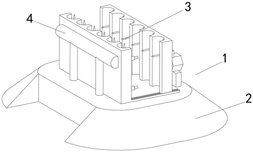
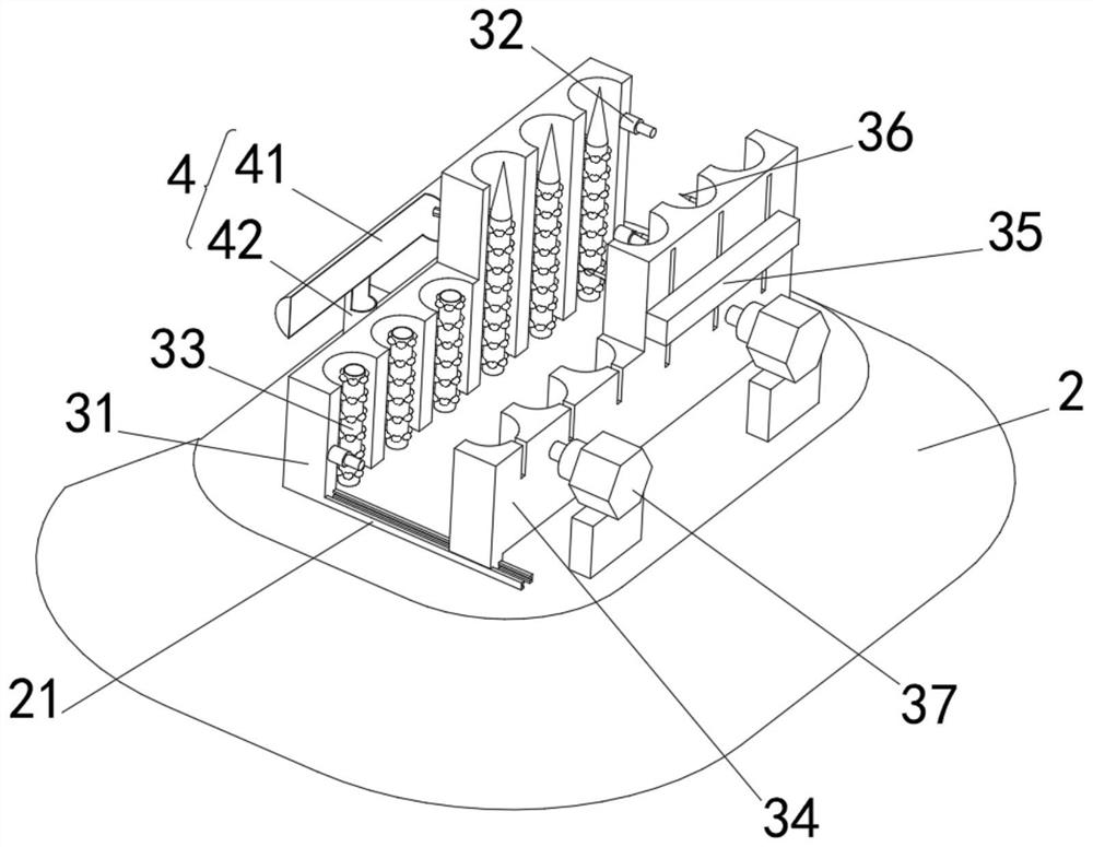
[0038] see Figure 1-2 , the present invention provides a technical solution: a quick punching device, including a quick punching device body 1 composed of a base 2, a clamp 3 and a pneumatic mechanism 4, the top of the base 2 is fixedly connected to the bottom of the clamp 3, and the bottom of the clamp 3 The left side is fixedly connected with the right side of the pneumatic mechanism 4, the top of the base 2 is fixedly connected with a slide rail 21, the pneumatic mechanism 4 includes an air storage cylinder 41, the bottom of the air storage cylinder 41 is connected with an air guide tube 42, and the bottom end of the air guide tube 42 is connected to the outside The air supply mechanism is connected, the outside of the air guide pipe 42 is fixedly connected with the inside of the base 2, the fixture 3 includes a fixed mold 31, the bottom of the fixed mold 31 is fixedly connected with the top of the base 2, and the right side of the fixed mold 31 is connected with the side o...
Embodiment 2
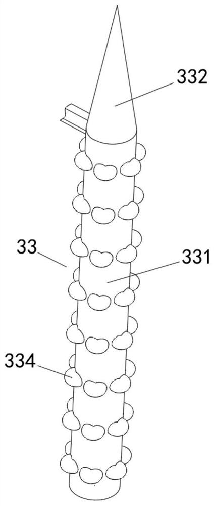
[0044] see Figure 1-4 , on the basis of Embodiment 1, the present invention provides a technical solution: the positioning mechanism 33 includes a positioning tube 331, the bottom of the positioning tube 331 is fixedly connected to the top of the base 2, and the inside of the air guide tube 42 passes through the thin tube and the positioning tube 331. The inside is connected, and the top of the positioning tube 331 is fixedly connected with a slider 332 .
[0045] An air outlet 333 is defined inside the positioning tube 331 , and an expander 334 is fixedly connected to the inside of the positioning tube 331 .
[0046] The slider 332 includes a conical block 3321 , a rotating ball 3322 is rotatably connected inside the conical block 3321 , and the bottom of the conical block 3321 is fixedly connected with the top of the positioning tube 331 .
[0047] In use, when the pipe fitting is inserted into the positioning mechanism 33, the slider 332 on the positioning mechanism 33 is...
Embodiment 3
[0049] see Figure 1-6 , on the basis of Embodiment 1 and Embodiment 2, the present invention provides a technical solution: an undulator 335 is provided inside the air outlet 333, and the undulator 335 includes a undulating ball 3351, and the inside of the undulating ball 3351 is adjusted by rotating the rod and positioning The inside of the tube 331 is connected in rotation, and the outside of the undulating ball 3351 is fixedly connected with a short-connection plate 3352 and a long-connection plate 3353 respectively.
[0050] The expander 334 includes an elastic block 3341, the outer side of the elastic block 3341 is fixedly connected with the inside of the positioning tube 331, the inside of the elastic block 3341 is provided with an expansion chamber 3342, and the inside of the expansion chamber 3342 is fixedly connected with an expansion bag 3343, and the inner wall of the expansion bag 3343 The inner sliding rod 3344 is fixedly connected by the rebound bar, and the rig...
PUM
 Abstract
Description
Claims
Application Information
 - R&D
- Intellectual Property
- Life Sciences
- Materials
- Tech Scout
- Unparalleled Data Quality
- Higher Quality Content
- 60% Fewer Hallucinations
Browse by: Latest US Patents, China's latest patents, Technical Efficacy Thesaurus, Application Domain, Technology Topic, Popular Technical Reports.
© 2025 PatSnap. All rights reserved.Legal|Privacy policy|Modern Slavery Act Transparency Statement|Sitemap|About US| Contact US: help@patsnap.com


