
Humanoid robot and its joints

A humanoid robot and joint technology, applied in the field of humanoid robots, can solve the problems of increasing the structural moment of inertia, reducing the strength of the mechanism, and difficult cable layout, etc., and achieve the effects of reducing inertia, reducing module weight, and compact structure

Active Publication Date: 2022-04-08
BEIJING INSTITUTE OF TECHNOLOGYGY
View PDF8 Cites 0 Cited by
  • Summary
  • Abstract
  • Description
  • Claims
  • Application Information

AI Technical Summary

Problems solved by technology

In the series mechanism, each drive module controls the movement of one joint. The structure is relatively simple, and different configuration schemes can be used for different joints. However, because one drive module needs to be installed at the output end of another drive, it increases the The moment of inertia of the structure, and the layout of the cables is more difficult
The parallel mechanism generally uses the differential motion of two drive modules to realize the compound motion of pitch and yaw. The drive module can be far away from the output end, which reduces the moment of inertia of the structure and the difficulty of cable layout. However, the existing parallel structure often uses the connecting rod The structure often reduces the strength of the whole mechanism, the movement space is relatively small, there are many singular points, or the differential movement is realized through other structures, the structure is easy to be complicated, and the assembly difficulty is high

Method used


Image

  • Humanoid robot and its joints
  • Humanoid robot and its joints
  • Humanoid robot and its joints

Examples


Embodiment 1

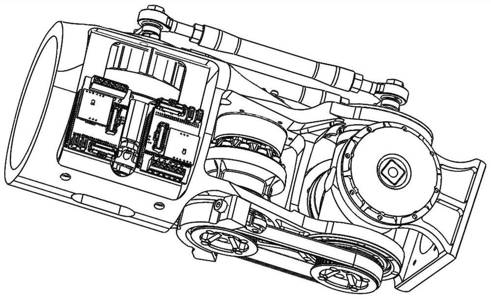
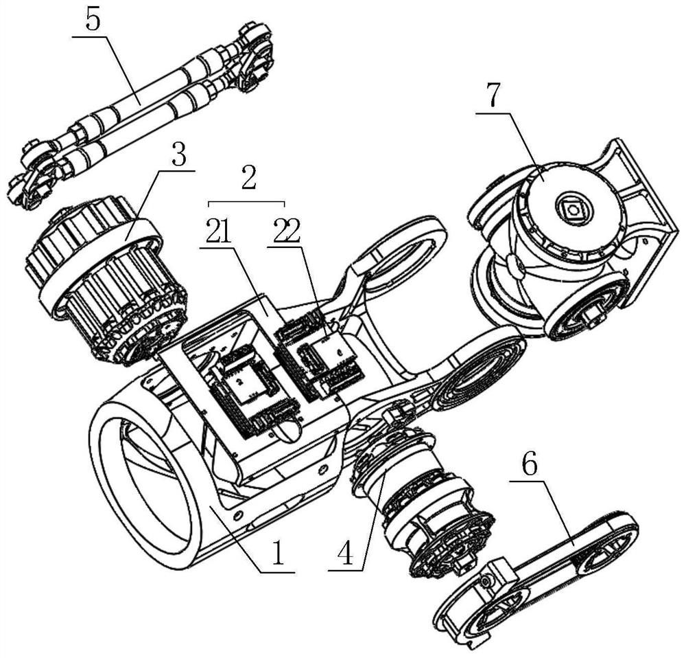
[0038] Such as figure 1 , 2As shown, the humanoid robot joint of the present invention is composed of a joint frame 1 , a driver module 2 , a first drive module 3 , a second drive module 4 , a connecting rod transmission module 5 , a synchronous belt transmission module 6 and a cross axis joint module 7 .

[0039] Such as figure 1 and figure 2 As shown, the joint frame 1 is used as the main frame of the humanoid robot joint, and adopts an integrated structure, which is similar to the shape of "冃" as a whole. The joint frame 1 away from the execution end is a hollow cylinder, and the joint frame 1 near the execution end is two opposite pieces. shape structure, and a pair of through holes are provided on the sheet structure; along the direction of the execution end, the first drive module 3, the second drive module 4 and the cross-axis joint module 7 are sequentially fixed in the joint frame 1, and the hollow cylindrical joint frame 1 is fixed with a driver module 2, and the...

Embodiment 2

[0051] A humanoid robot, including the humanoid robot joints in Embodiment 1, whose structural features have been described in Embodiment 1 in detail, and will not be repeated here.


PUM


Abstract

The invention provides a humanoid robot and its joints, belonging to the technical field of humanoid robots. The humanoid robot joint of the present invention includes a joint frame with an integrated structure, a first drive module, a second drive module, a connecting rod transmission module, a synchronous belt transmission module and a cross axis joint module, which are sequentially fixed in the joint frame along the direction of the execution end There are a first driving module, a second driving module and a cross shaft joint module, and the connecting rod transmission module and the synchronous belt transmission module are located on both sides of the joint frame. The invention has the advantage of reducing the moment of inertia by keeping the driving module away from the execution end in a parallel structure, and also has different configuration schemes for different degrees of freedom in the series mechanism according to the work requirements; the overall structure has a high degree of modularization and integration, High moment-to-weight ratio and high structural strength.

Description

technical field [0001] The invention relates to the technical field of humanoid robots, in particular to humanoid robots and joints thereof. Background technique [0002] In order to save space and facilitate decoupling calculations, the combined joints of robots that can realize the compound motion of pitch and yaw at present require the rotation axes of the two degrees of freedom to intersect. Serial or parallel mechanisms are often used to realize this function. In the series mechanism, each drive module controls the movement of one joint. The structure is relatively simple, and different configuration schemes can be used for different joints. However, because one drive module needs to be installed at the output end of another drive, it increases the The moment of inertia of the structure, and the layout of cables is more difficult. The parallel mechanism generally uses the differential motion of two drive modules to realize the compound motion of pitch and yaw. The driv...

Claims


Application Information

Patent Timeline
Patent Type & Authority Patents(China)
IPC IPC(8): B25J17/02B25J9/12
CPCB25J17/0258B25J9/126B25J9/104B25J9/109
Inventor 朱鑫黄强余张国陈学超高峻峣黄岩
Owner BEIJING INSTITUTE OF TECHNOLOGYGY
Learn More