Workpiece transfer device for machining

A transfer device and mechanical processing technology, applied in the direction of conveyor objects, mechanical conveyors, transportation and packaging, etc., can solve problems such as relative displacement of conveyor belts, and achieve the effects of improved transfer efficiency, cost saving, and simple structure

Pending Publication Date: 2021-06-01
湖州师范学院求真学院
View PDF9 Cites 0 Cited by
  • Summary
  • Abstract
  • Description
  • Claims
  • Application Information

AI Technical Summary

Problems solved by technology

[0004] The embodiment of the present invention provides a workpiece transfer device for mechanical processing, which can solve the problem of relative displacement caused by the conveyor belt in the prior art

Method used


Image

  • Workpiece transfer device for machining
  • Workpiece transfer device for machining
  • Workpiece transfer device for machining

Examples


Embodiment 1

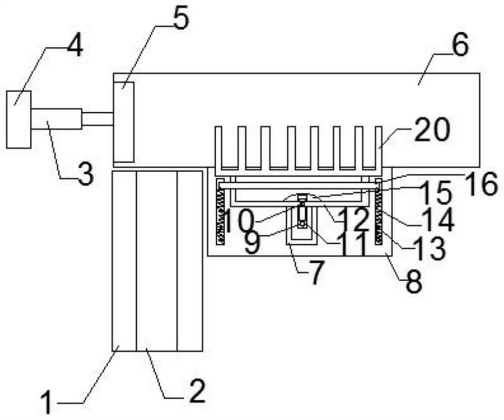
[0033] Such as figure 1 As shown, the transmission device includes a conveyor belt 2. Baffle plates 1 are provided on both sides of the conveyor belt 2. The baffle plate 1 is higher than the conveyor belt 2. One end of the conveyor belt 2 corresponds to the transfer table 6. The transfer device is used to transport the workpiece to the transfer table 6.

[0034] Pushing device comprises: base 4, base 4 top is provided with push rod 3, and the free end of push rod is provided with push block 5. The height of the base 4 is set to match the height of the transfer platform 6 . Pushing device is used for pushing the workpiece of transfer table 6 into the first small "U" shaped frame.

[0035] The transfer device, the transfer device includes: a horizontal plate 8, the horizontal plate 8 is arranged at the bottom of the transfer platform 6, there is a pole 17 supporting the transfer platform 6 at the bottom of the horizontal plate, the first rectangular slide rail 7 is arranged on ...

Embodiment 2

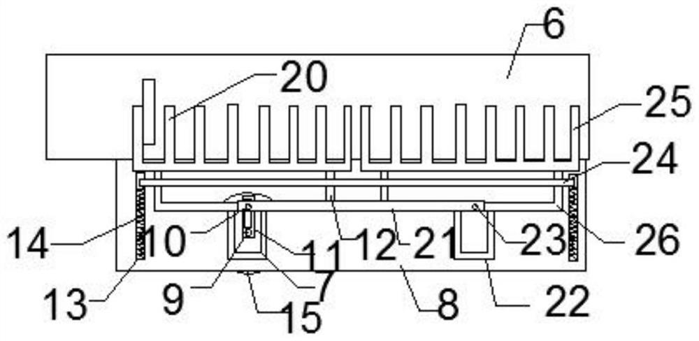
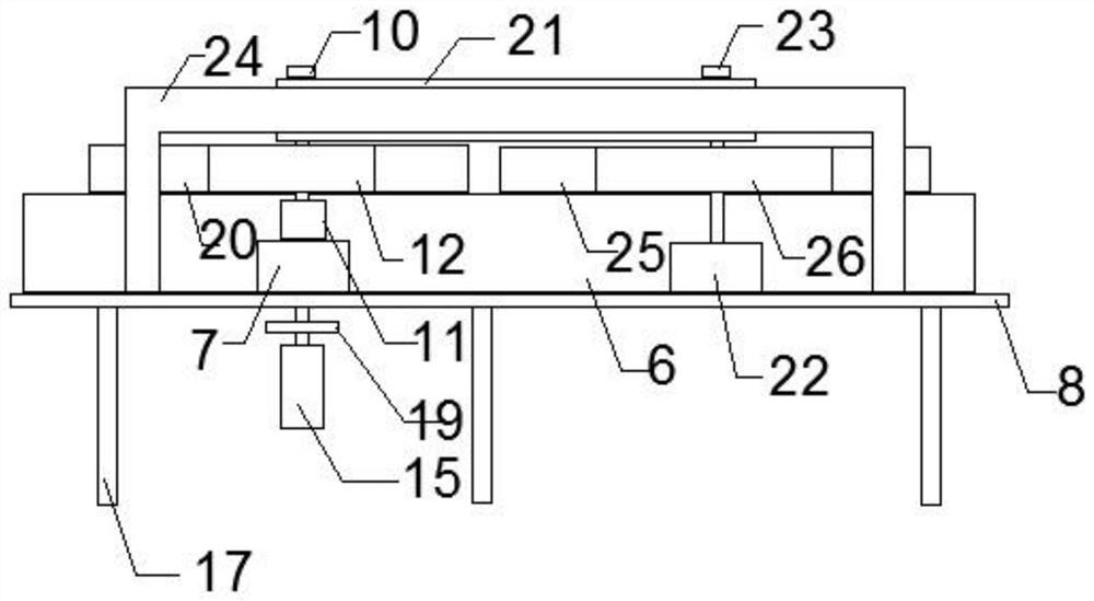
[0037] Such as figure 2 and 3 As shown, on the basis of Embodiment 1, the transfer device also includes a shipping device on the same side of the transfer platform, including: a second rectangular slide rail 22 on which a second slide block 23 is slid A second "U"-shaped frame 25 is arranged above the second slider 23, and a connecting rod 21 is connected between the first slider 10 and the second slider 23. The second "n" type limit rod 24 is slidably arranged on the transfer platform 6 and is located above the first "U" type frame 20 and the second "U" type frame 25.

Embodiment 3

[0039] On the basis of Embodiments 1 and 2, the bottom ends of the first "n" type limit rod 16 and the second "n" type limit rod 24 are provided with "I" type slide rails, and the "I" type slide rails Slide in groove 13, be provided with spring 14 between " I " type slide rail and chute 13 one ends.


PUM


Abstract

The invention discloses a workpiece transfer device for machining, and relates to the technical field of machining. The workpiece transfer device comprises a transfer table, a conveying device, a pushing device, a transverse plate, a first U-shaped frame, a second U-shaped frame, a first rectangular sliding rail, a first strip-shaped sliding rail, a first sliding block and a driving device. The conveying device is used for conveying workpieces to the transfer table. The pushing device is used for pushing the workpieces on the transfer table. The transverse plate is arranged at the bottom of the transfer table. Deflector rods are arranged in the first U-shaped frame at equal intervals, and the first U-shaped frame is located above the transfer table. The second U-shaped frame is arranged at the side of the first U-shaped frame. The first rectangular sliding rail is arranged above the transverse plate. The first strip-shaped sliding rail is located above the first rectangular sliding rail. The first sliding block is slidably arranged in the first strip-shaped sliding rail, one end of the first sliding block is connected with the bottom of the second U-shaped frame, and the other end of the first sliding block is slidably connected in the first rectangular sliding rail. The driving device is arranged at the bottom of a first rotating shaft, and the first rotating shaft is fixedly connected with one end of the first sliding block. The workpiece transfer device can solve the problem of relative displacement of a conveyor belt in the transfer process in the prior art, and is simple in structure and easy to popularize.

Description

technical field [0001] The invention relates to the technical field of mechanical processing, in particular to a workpiece transfer device for mechanical processing. Background technique [0002] Machining refers to the process of changing the shape or performance of a workpiece through a mechanical device. According to the difference in processing method, it can be divided into cutting processing and pressure processing. In the process of producing and processing mechanical workpieces, the workpieces need to undergo processing steps such as die-casting, grinding, and drilling in sequence. During the above-mentioned processing steps, the workpieces need to be transmitted sequentially according to the above-mentioned processing procedures. [0003] At present, the transfer of machining workpieces mainly includes manual handling, manipulator grabbing and conveyor belt transmission. Manual handling mainly has the method of adding manpower to the vehicle, because loading and u...

Claims


Application Information

Patent Timeline
IPC IPC(8): B65G35/00B65G23/04B65G47/22B65G37/00B65G47/82
CPCB65G35/00B65G23/04B65G47/22B65G37/00B65G47/82
Inventor 李世康王磊陈婷婷郭宇
Owner 湖州师范学院求真学院
Why Eureka
Try Eureka