Dust removal device and mechanism and automatic dust removal method

A technology of automatic dust removal and dust removal device, applied in separation methods, chemical instruments and methods, transportation and packaging, etc., can solve the problems of complicated procedures, waste of raw materials, low work efficiency, etc., achieve compact and portable structure, improve work efficiency, and improve The effect of crystal growth quality

Active Publication Date: 2021-06-01
SICC CO LTD
View PDF5 Cites 0 Cited by
  • Summary
  • Abstract
  • Description
  • Claims
  • Application Information

AI Technical Summary

Problems solved by technology

[0004] The above-mentioned dust removal method is inefficient and requires workers to perform multiple operations at the same time. The vacuum cleaner needs to be manually turned on and off every time it is used. Suck it away, waste raw materials and increase the cost; in addition, the vacuum cleaner is too large, the pipeline is long, it takes up space, and it is inconvenient to clean

Method used


Image

  • Dust removal device and mechanism and automatic dust removal method
  • Dust removal device and mechanism and automatic dust removal method
  • Dust removal device and mechanism and automatic dust removal method

Examples


Embodiment 1

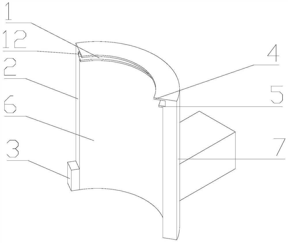
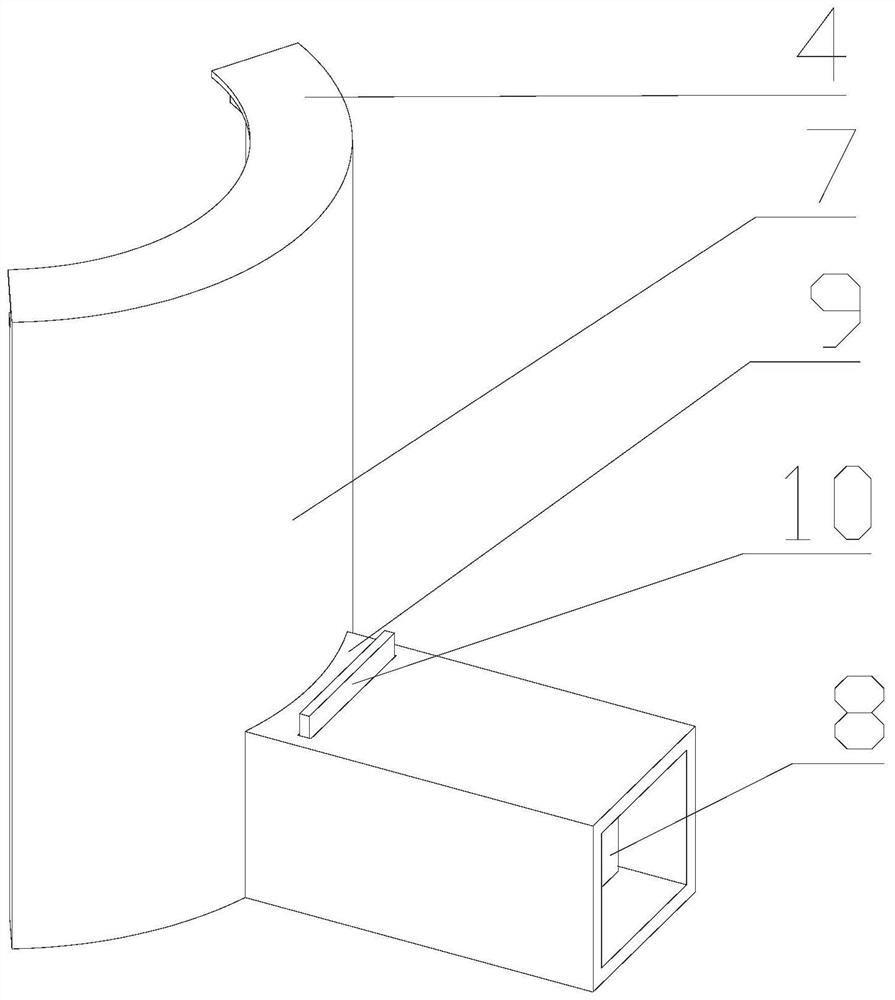
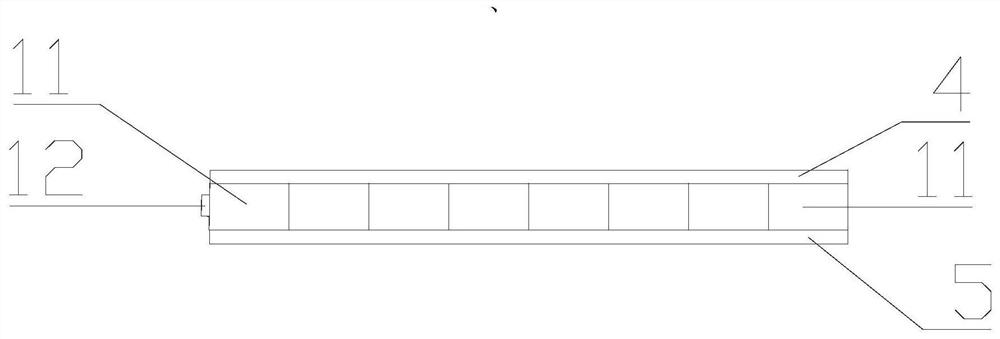
[0055] refer to figure 1 , the embodiment of the present application discloses a dust removal device, the dust removal device includes a housing and an induction unit 3, the housing forms an airflow channel 2 with an air inlet 1, and the airflow channel 2 communicates with the air inlet of the airflow generating unit 8, The part to be dusted is placed in the airflow area formed by the air inlet 1; the sensing unit 3 is connected to the airflow generating unit 8, and the part to be dusted is placed in the sensing area of ​​the sensing unit 3, and the airflow generating unit 8 is activated by the controller to form an airflow along the air inlet 1. , the airflow channel 2, the air inlet and the airflow flowing from the airflow generating unit 8; if the object to be removed is removed from the sensing area of ​​the sensing unit 3, the controller closes the airflow generating unit 8. The air flow generating unit 8 is not a part of the device, it can be connected to the outside of ...

Embodiment 2

[0072] The embodiment of the present application discloses a dust removal method, which includes the following steps: providing powder, a crucible, a housing, an induction unit 3 and an airflow generating unit 8, the housing forms an airflow channel 2 with an air inlet 1, and the airflow Channel 2 communicates with the air inlet of airflow generating unit 8; when the crucible is placed in the sensing area of ​​induction unit 3, the output signal of induction unit 3 controls the start of airflow generating unit 8, forming a Add powder to the crucible to start dust removal; stop adding powder to the crucible, move the crucible out of the sensing area of ​​the sensing unit 3, and the sensing unit 3 outputs a signal to control the airflow generating unit 8 Close, the dust removal is finished.

[0073] This method is realized by using the dust removal device and mechanism of Embodiment 1. The crucible is placed about 5 mm away from the front side wall of the housing. At this time, ...


PUM

PropertyMeasurementUnit
angleaaaaaaaaaa

Abstract

The invention discloses a dust removal device and mechanism and an automatic dust removal method and belongs to the technical field of production auxiliary equipment. The automatic dust removal method comprises the following steps that a powder material, a crucible, a shell, an induction unit and an airflow generation unit are provided, an airflow channel with a wind inlet is formed in the shell, and the airflow channel communicates with an air inlet of the airflow generation unit; the crucible is arranged in an induction area of the induction unit, the induction unit outputs signals to control the airflow generation unit to be started, airflow flowing along the wind inlet, the airflow channel, the air inlet and the airflow generation unit is formed, the powder material is added into the crucible, and dust removal is started; and adding the powder material into the crucible is stopped, the crucible is moved out of the induction area of the induction unit, the induction unit outputs signals to control the airflow generation unit to be turned off, and the dust removal is finished. By means of the automatic dust removal method, manual handheld operations are not needed any more, automatic induction dust removal is achieved, energy sources are saved, and the working efficiency is greatly improved.

Description

technical field [0001] The application relates to a dust removal device, a mechanism and an automatic dust removal method, belonging to the technical field of production auxiliary equipment. Background technique [0002] In the existing production process, whether it is the loading process or the production and processing process, a lot of dust is often generated, which will affect the processing process and product quality on the one hand; on the other hand, it will also cause pollution and endanger the health of workers. [0003] For example, in the production process of semiconductor silicon carbide, silicon carbide powder is usually added to the crucible in advance, and then the crystal growth process starts. When the operator charges the crucible, more dust will be generated, which will cause defects in the crystal and affect the quality of the crystal growth. At present, when loading, the worker holds the vacuum cleaner head with one hand, turns on the vacuum cleaner,...

Claims


Application Information

Patent Timeline
Patent Type & Authority Applications(China)
IPC IPC(8): F27D17/00B01D46/00B01D46/10
CPCF27D17/001F27D17/008B01D46/10B01D46/66B01D46/88
Inventor 郭德华李钊王洪港庄齐帅万冠军
Owner SICC CO LTD
Why Eureka
Try Eureka