Transformer type force sensor

A force sensor and transformer-type technology, applied in the field of transformer-type force sensors, can solve the problems of not being able to fully meet the electro-hydraulic control requirements of high-horsepower tractors, and achieve the effect of reducing magnetic permeability and improving sensitivity

Active Publication Date: 2021-06-01
SHANDONG UNIV +1
View PDF12 Cites 0 Cited by
  • Summary
  • Abstract
  • Description
  • Claims
  • Application Information

AI Technical Summary

Problems solved by technology

[0007] Although the existing technology can improve the sensitivity of the sensor, it cannot fully meet the electro-hydraulic control requirements of high-horsepower tractors. In order to further improve the sensitivity of the sensor and meet the requirements of electro-hydraulic control, a transformer-type force sensor with higher sensitivity is urgently needed

Method used


Image

  • Transformer type force sensor
  • Transformer type force sensor
  • Transformer type force sensor

Examples


Embodiment 1

[0024] This embodiment discloses a transformer type force sensor;

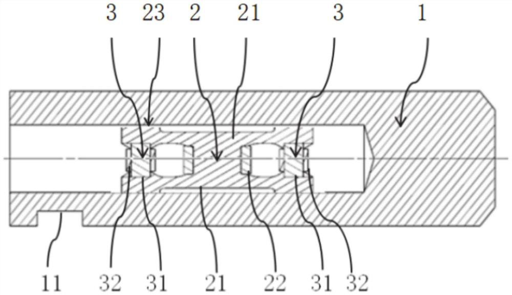
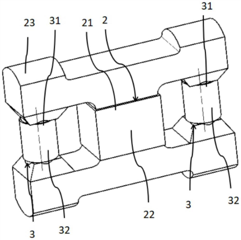
[0025] The transformer-type force sensor includes a force-bearing cylinder 1, and an excitation core 2 is installed in the force-bearing cylinder 1. The excitation core 2 includes an excitation pole 21, and an excitation coil 22 is wound around the periphery of the excitation pole 21. The number of turns and the connection method of the excitation coil 22 can be set according to actual needs, which is well known to those skilled in the art and will not be repeated here.

[0026] Two inductive magnetic cores 3 are installed symmetrically on both axial sides of the excitation magnetic core 2 in the bearing cylinder 1. The inductive magnetic cores 3 are two ferromagnets with the same size but different materials, which are respectively positive magnetostrictive Material ferromagnet and negative magnetostrictive material ferromagnet. Each induction core 3 includes an induction pole 31, and an induction coil 32 is...

Embodiment 2

[0033] In this embodiment, the excitation installation surface 23 is located on both sides of the excitation core 2 and the induction core 3 , there are two excitation installation surfaces 23 , and each excitation installation surface 23 is integrally formed. The top surface of the excitation installation surface 23 is in contact with the bearing cylinder 1 , and the height of the top surface of the excitation installation surface 23 corresponding to the excitation core 2 is lower than the top surface height of the excitation installation surface 23 corresponding to the induction core 3 . The space between the exciting magnetic core 2 and the two induction magnetic cores 3 is hollowed out.

Embodiment 3

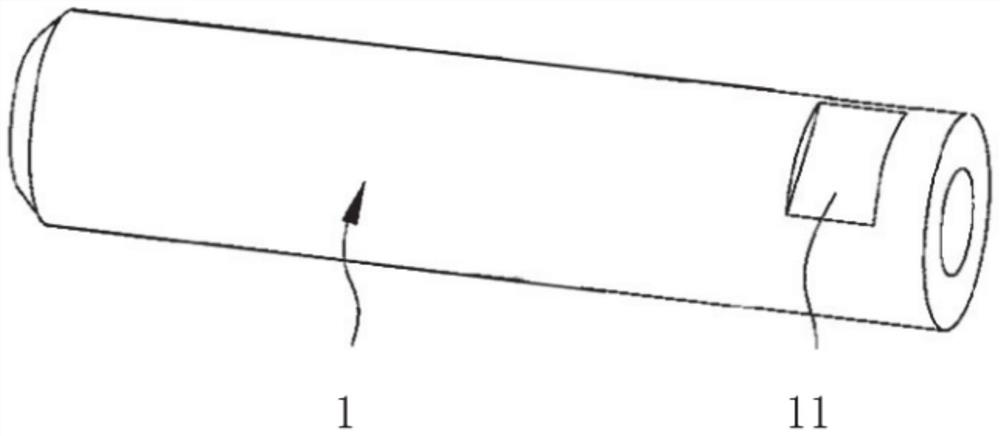
[0035] The load-bearing cylinder 1 is processed from a circular tube. Of course, the load-bearing cylinder 1 can also be formed by drilling a pin shaft, and a step or slot structure 11 can be added on its outer peripheral surface for positioning and installation.

[0036] A positioning structure 11 is provided on the outer peripheral surface of the load-bearing cylinder 1, and the positioning structure 11 is a step or a slot for positioning and installation.

[0037] The load-bearing cylinder 1 is only used to carry and transmit external force, and it does not exist as a part of the magnetic circuit itself. The magnetic flux passing through the sleeve can be classified within the range of magnetic flux leakage. Therefore, the sleeve should adopt magnetic permeability It is made of materials with a low rate, or a magnetic isolation part is added in the contact area between the sleeve and the magnetic core to reduce the influence of magnetic flux leakage.


PUM


Abstract

The invention provides a transformer type force sensor. The transformer type force sensor comprises a force bearing cylinder; an excitation magnetic core is installed in the force bearing cylinder; the excitation magnetic core comprises an excitation magnetic pole; an excitation coil is installed on the periphery of the excitation magnetic pole in a winding mode; two induction magnetic cores are symmetrically installed in the force bearing cylinder and located on the two axial sides of the excitation magnetic core; the induction magnetic core is composed of two ferromagnets which are the same in size but different in material; and the two ferromagnets are respectively a positive magnetostrictive material ferromagnet and a negative magnetostrictive material ferromagnet.

Description

technical field [0001] The disclosure belongs to the technical field of force sensors, and in particular relates to a transformer-type force sensor. Background technique [0002] The statements in this section merely provide background information related to the present disclosure and do not necessarily constitute prior art. [0003] In the electro-hydraulic lifting control process of high-horsepower tractors, soil resistance is one of the main control signals. As the main signal receiving device of the electro-hydraulic lift control, the force sensor plays an irreplaceable role in it, and is one of the core components of the electro-hydraulic lifter. [0004] The performance of the force sensor will directly affect the working quality of the suspended agricultural implements. The working environment of the force sensor requires that it not only has a large load bearing capacity, but also has a good linear output under the premise of slight strain. , which has high sensiti...

Claims


Application Information

Patent Timeline
Patent Type & Authority Applications(China)
IPC IPC(8): G01L1/12
CPCG01L1/125
Inventor 李瑞川刘畅谢玉东徐继康刘延俊黄传真郭坤李剑锋贾克涛
Owner SHANDONG UNIV
Why Eureka
Try Eureka