Shifting fork magnetic assembly

A technology of magnetic components and magnets, applied in the direction of magnetic objects, magnets, permanent magnets, etc., can solve problems such as affecting the overall operation, affecting the stability of magnet clamping, and inaccurate magnetic field signals, reducing the probability of demagnetization and improving connection stability. Sex, the effect of reducing the overall size

Active Publication Date: 2021-06-01
杭州浩瀚精密科技有限公司
View PDF7 Cites 0 Cited by
  • Summary
  • Abstract
  • Description
  • Claims
  • Application Information

AI Technical Summary

Problems solved by technology

[0004] In the related technology, the magnet is mainly connected to the substrate by clamping. In the actual use process, the vibration will affect the stability of the magnet clamping, especially the position stability. In other words, once the position shifts, the subsequent It will lead to inaccurate magnetic field signals detected by the position sensor, which will affect the overall operation

Method used


Image

  • Shifting fork magnetic assembly
  • Shifting fork magnetic assembly
  • Shifting fork magnetic assembly

Examples


Embodiment 1

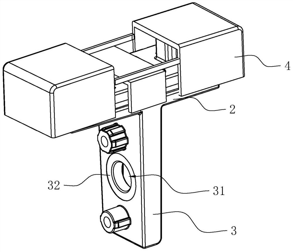
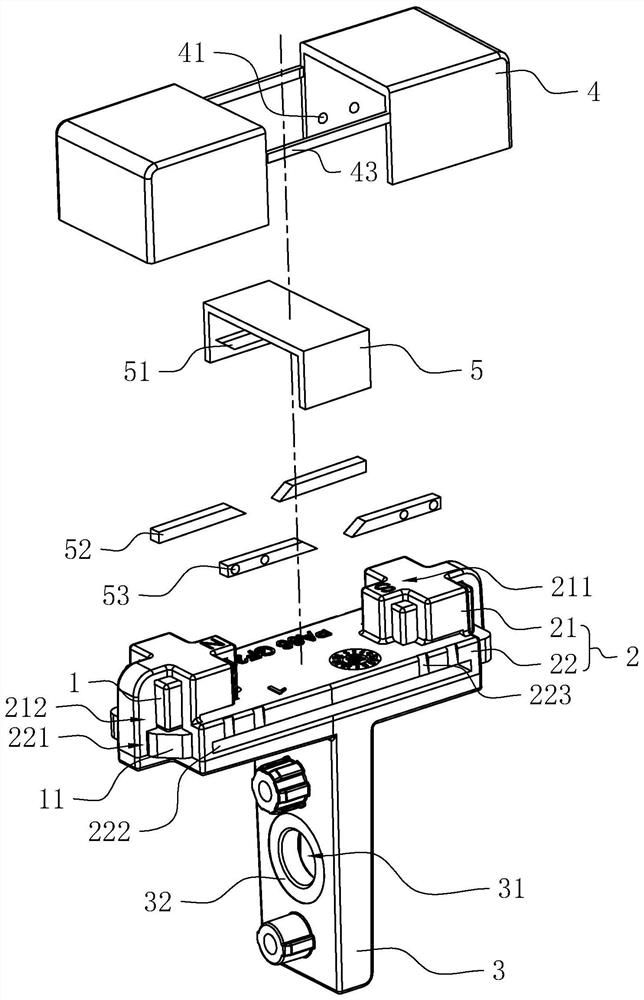
[0041] refer to figure 1 and figure 2 , the shift fork magnetic assembly includes a base body and a magnet 1, and the roughly T-shaped base body includes a plastic coating part 2 and a mounting part 3, and the plastic coating part 2 and the mounting part 3 are integrally formed, all of which can be made of nylon, but not limited to Nylon material; the overmolding part 2 includes two first overmolding bodies 21 and a second overmolding body 22, the first overmolding body 21 is located on the side of the second overmolding body 22 away from the mounting part 3, each first A magnet 1 is overmolded in the overmolding body 21 , and a heat-conducting yoke plate 11 is overmolded in the second overmolding body 22 , and one side of the supporting heat-conducting yoke plate 11 abuts against one side of the magnet 1 .

[0042] The overmolding part 2 is provided with two marking areas 211 marked with cathode and anode respectively, and the two marking areas 211 correspond to two magnets...

Embodiment 2

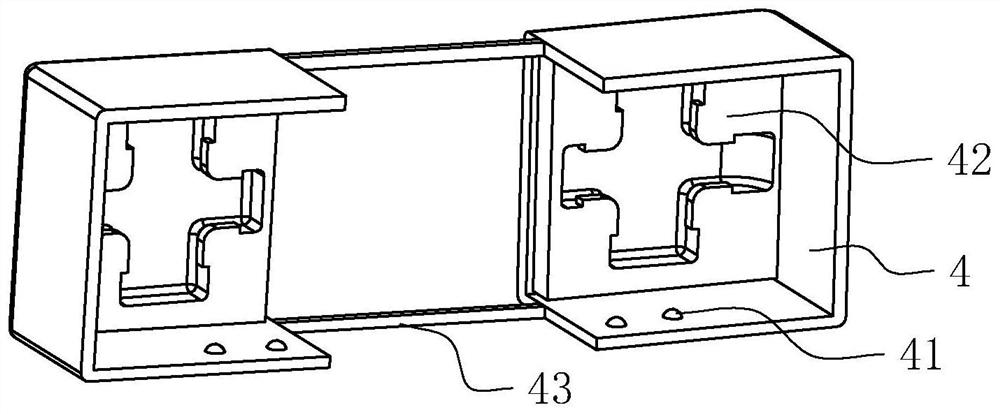
[0054] refer to Figure 4 The difference between this embodiment and Embodiment 1 is that the reserved positioning groove 212 left due to the positioning of the magnet 1 in the mold is located on the periphery of the first overmolding body 21, and the first overmolding body 21 is in the shape of X-shaped cross-wrapped plastic.


PUM


Abstract

The invention relates to a shifting fork magnetic assembly. The shifting fork magnetic assembly comprises a base body and a magnet, wherein the base body comprises a plastic coating part and a mounting part, wherein the magnet is coated with the plastic coating part, the mounting part is connected to the plastic coating part, a reserved positioning groove is formed in the outer wall of the plastic coating part, and the reserved positioning groove communicates with the interior of the plastic coating part. The magnet is positioned before plastic coating, so the initial position of the plastic-coated magnet is accurate; and meanwhile, the magnet is plastic-coated, so the problem that a magnetic field signal detected by a position sensor is inaccurate due to the deviation of the magnet in a later use process is not easy to occur, and the connection stability of the magnet and the base body is improved.

Description

technical field [0001] The application relates to the production field of a shift fork magnetic assembly, in particular to a shift fork magnetic assembly. Background technique [0002] The transmission shift fork is a part of the automobile gearbox. It is connected to the shift handle and is located at the lower end of the handle. The middle shift wheel is moved to change the input / output speed ratio. The shift fork is mainly used for clutch shifting. Specifically, it is used in the transmission to push the synchronizer gear sleeve to engage and separate from the shift gear to realize the gear change of the transmission. The magnet assembly of the shift fork is a part of the transmission that is fixed on the shift fork and provides a magnetic field signal source. The position sensor installed on the transmission housing is a component used in the transmission to monitor the output of the magnetic field signal of the shift fork and perform signal conversion. [0003] The str...

Claims


Application Information

Patent Timeline
Patent Type & Authority Applications(China)
IPC IPC(8): H01F7/02H01F27/22F16H63/32
CPCH01F7/0221H01F7/0294H01F27/22F16H63/32
Inventor 卢展江
Owner 杭州浩瀚精密科技有限公司
Why Eureka
Try Eureka