Current overload protection device for replacement of electric equipment in power distribution cabinet

A technology for electrical equipment and current overload, applied in the cooling/ventilation of substations/switchgear, switchgear, AC network load balancing, etc. Cable oxidation corrosion and other problems, to achieve the effect of reducing power loss, reducing reactive current, and ensuring stability

Inactive Publication Date: 2021-06-01
岑理辉
View PDF0 Cites 0 Cited by
  • Summary
  • Abstract
  • Description
  • Claims
  • Application Information

AI Technical Summary

Problems solved by technology

[0003] Some electrical equipment installed inside the power distribution cabinet, such as fluorescent lamps, transformers and motors, are inductive electrical loads. When replacing and installing electrical equipment such as fluorescent lamps, the current of the internal circuit of the power distribution cabinet will change in a short time , which in turn causes the voltage of the circuit to fluctuate, increasing the reactive power and wasting a lot of electric energy. Secondly, the short-term increase of the current will increase the heat generated by the circuit, and the increase in temperature will accelerate the oxidation and corrosion of the joints of the electrical equipment cables. Shorten the service life of the cable, therefore, those skilled in the art provide a current overload protection device when the electrical equipment inside the power distribution cabinet is replaced, to solve the problems raised in the above-mentioned background technology

Method used


Image

  • Current overload protection device for replacement of electric equipment in power distribution cabinet
  • Current overload protection device for replacement of electric equipment in power distribution cabinet
  • Current overload protection device for replacement of electric equipment in power distribution cabinet

Examples


Embodiment Construction

[0020] The following will clearly and completely describe the technical solutions in the embodiments of the present invention with reference to the accompanying drawings in the embodiments of the present invention. Obviously, the described embodiments are only some, not all, embodiments of the present invention. Based on the embodiments of the present invention, all other embodiments obtained by persons of ordinary skill in the art without making creative efforts belong to the protection scope of the present invention.

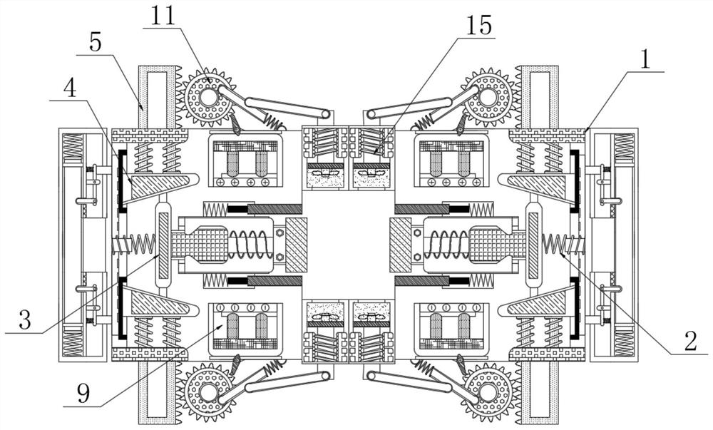
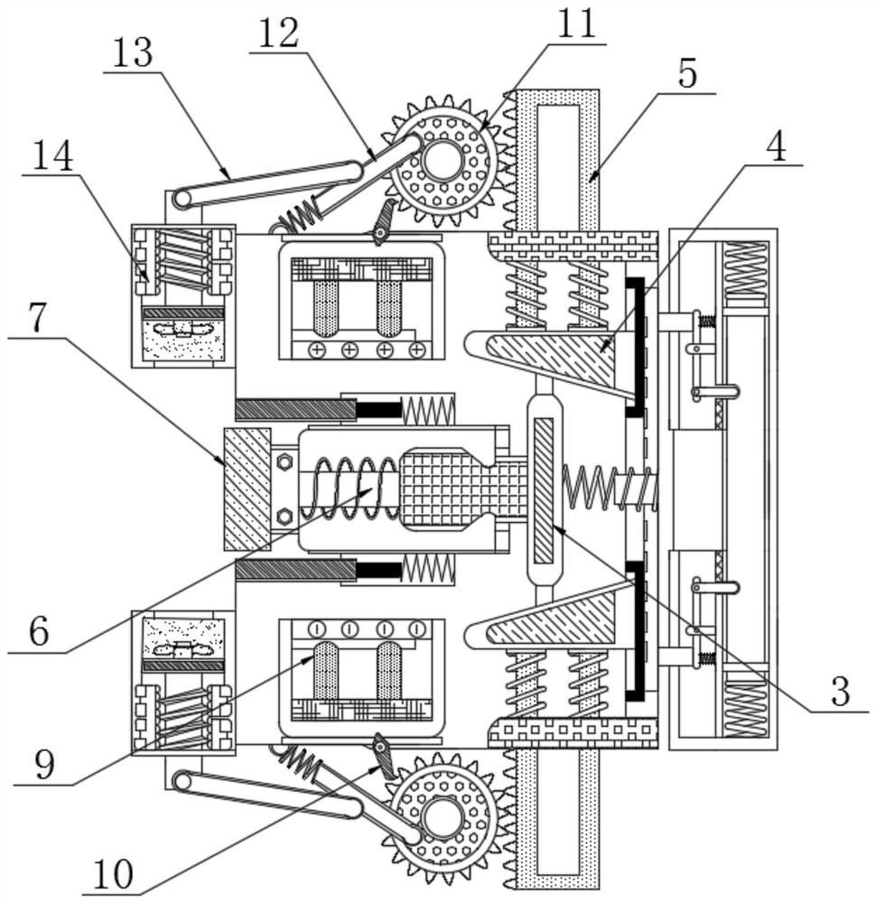
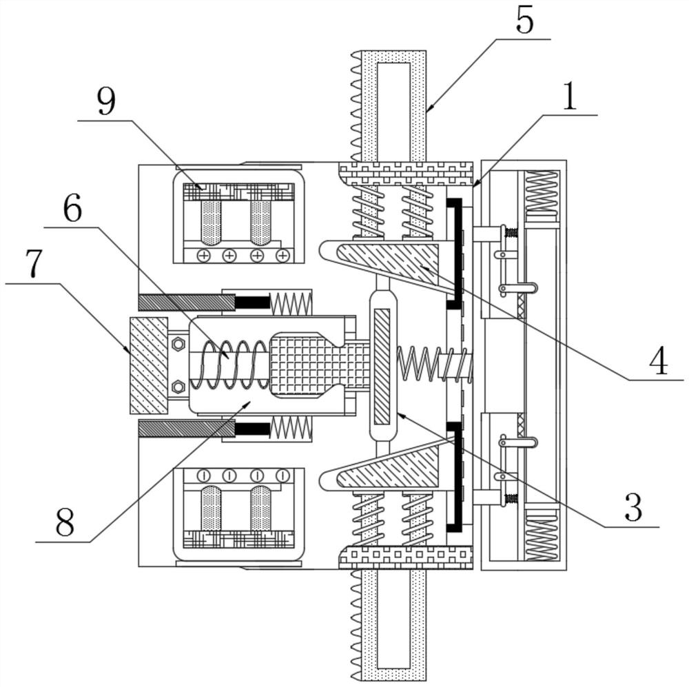
[0021] see Figure 1-5 , a current overload protection device for replacing electrical equipment inside a power distribution cabinet, comprising an outer protective shell 1, the inner wall of the outer protective shell 1 is fixedly connected with a first spring 2, and one end of the first spring 2 is fixedly connected with a moving plate 3 , both ends of the moving plate 3 are movably connected with an adjustment block 4, the outer surface of the adjustment bl...


PUM


Abstract

The invention relates to the technical field of power distribution cabinets, in particular to a current overload protection device for replacement of electric equipment in a power distribution cabinet; a first spring is fixedly connected to the inner wall of an outer protection shell, a moving plate is fixedly connected to one end of the first spring, and adjusting blocks are movably connected to the two ends of the moving plate; a toothed plate is fixedly connected to the outer surface of the adjusting block and movably penetrates through the exterior of the outer protection shell, a supporting plate is fixedly connected to the outer surface of the moving plate, a mounting clamping seat is fixedly connected to one end of the supporting plate, and a dielectric plate is fixedly connected to the rear surface of the supporting plate; electrode plates are fixedly connected to the inner walls of the two sides of the outer protection shell and located on the two sides of the dielectric plate, the electrode plates can output a certain current in a short time without making the circuit reduce the voltage immediately, the problem that the power supply voltage fluctuates along with the fluctuation of the load current is solved, namely, a large number of reactive currents are reduced. And the electric energy loss of the line is reduced to the minimum.

Description

technical field [0001] The invention relates to the technical field of power distribution cabinets, in particular to a current overload protection device for replacing electrical equipment inside the power distribution cabinet. Background technique [0002] The switchboard, also known as the current overload protection device when the electrical equipment inside the power distribution cabinet is replaced, is a device for concentrating, switching, and distributing electric energy. Composed of sub-components, the main purpose of the switchboard is to facilitate power outage and power transmission, and to play the role and function of measurement and protection. [0003] Some electrical equipment installed inside the power distribution cabinet, such as fluorescent lamps, transformers and motors, are inductive electrical loads. When replacing and installing electrical equipment such as fluorescent lamps, the current of the internal circuit of the power distribution cabinet will ...

Claims


Application Information

Patent Timeline
Patent Type & Authority Applications(China)
IPC IPC(8): H02B3/00H02B1/56H02J3/12H02J3/28
CPCH02B1/565H02B3/00H02J3/12H02J3/28
Inventor 岑理辉龙沛文万武
Owner 岑理辉
Why Eureka
Try Eureka