
A device for removing green skin of walnut processing
The technology of green peel and walnut is applied in the field of green peel removal device for walnut processing, which can solve the problems of low efficiency, easy to be cut by knives, difficult to remove by hand, etc., and achieve the effect of convenient use.
- Summary
- Abstract
- Description
- Claims
- Application Information
AI Technical Summary
Problems solved by technology
Method used
Image

Examples
Embodiment 1
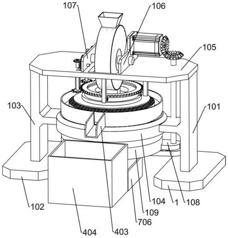
[0030] A walnut processing green peel removal device, such as figure 1 As shown, it includes a support frame, a power mechanism and a peeling mechanism. The support frame includes a first base plate 1, a first vertical support 101, a second base plate 102, a second vertical support 103, a ring frame 104, an upper horizontal plate 105, The first support plate 106, the second support plate 107, the fixing plate 108 and the drum frame 109, the upper sides of the first bottom plate 1 and the second bottom plate 102 are fixedly connected with the first vertical support 101 and the second vertical support 103, the upper horizontal The lower side of the plate 105 is fixedly connected to the upper ends of the first vertical support 101 and the second vertical support 103, the outer side of the ring frame 104 is fixedly connected to the inner side of the first vertical support 101 and the second vertical support 103, and the drum frame 109 is fixedly connected Inside the ring frame 104...
Embodiment 2
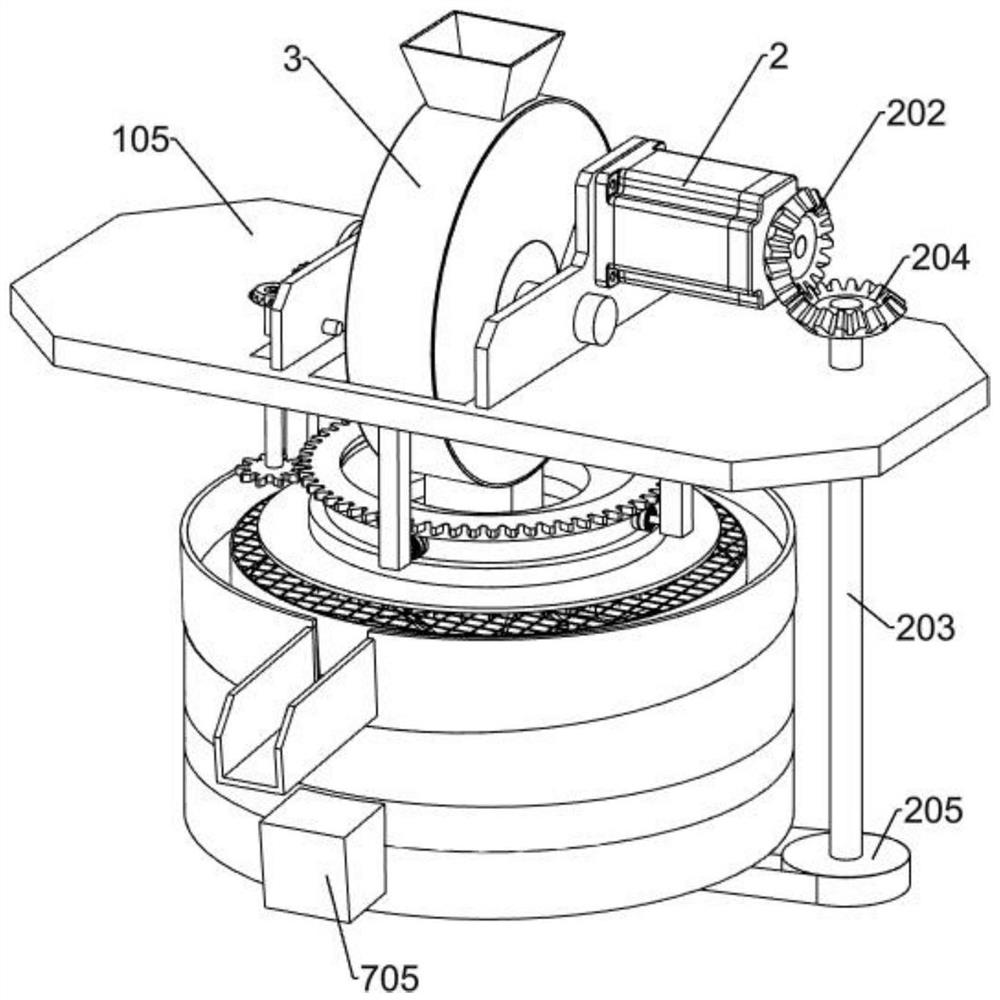
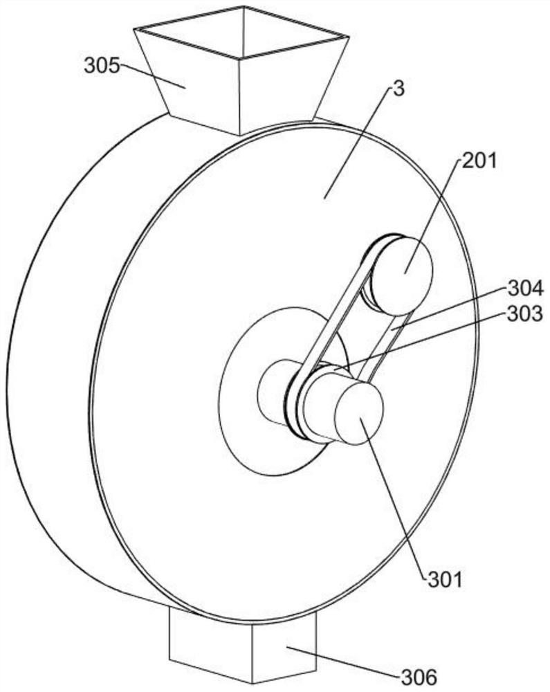
[0033]On the basis of Example 1, as Figure 2-Figure 4 As shown, the power mechanism includes a motor 2, a driving pulley 201, a first bevel gear 202, a vertical shaft 203, a second bevel gear 204 and a large pulley 205. The motor 2 is fixedly connected to the right side of the rear end of the first support plate 106, The driving pulley 201 is fixedly connected to the power output shaft of the left part of the motor 2; the first bevel gear 202 is fixedly connected to the power output shaft of the right part of the motor 2; The second bevel gear 204 is fixedly connected to the upper end of the vertical shaft 203 , the second bevel gear 204 meshes with the first bevel gear 202 , and the large pulley 205 is fixedly connected to the lower end of the vertical shaft 203 .
[0034] When the power is turned on, the motor 2 starts to rotate, the motor 2 drives the driving pulley 201 to rotate, and at the same time drives the first bevel gear 202 to rotate, the first bevel gear 202 driv...
Embodiment 3
[0038] On the basis of Example 2, as Figure 5-Figure 11 As shown, the screening mechanism includes a circular screen frame 4, an inclined discharge plate 401, a circular screen 402, a discharge guide plate 403 and a first collection bin 404. The lower end of the screen circular frame 4 is fixedly connected to the drum On the upper end of the frame 109, the inclined discharge plate 401 is fixedly connected to the inner side of the screen circular frame 4, the lower part of the circular screen 402 is fixedly connected to the inner side of the inclined discharge plate 401, and the rear end of the discharge guide plate 403 is fixedly connected to the screen On the outer side of the mesh circular frame 4, the first collection bin 404 is arranged on the discharge guide plate 403 to cooperate with it.
[0039] After the green skin of the walnut is removed, it falls from the discharge port 306 to the circular sieve 402, the broken green skin falls from the hole of the circular sieve ...
PUM
 Abstract
Description
Claims
Application Information