
Welding and dispensing equipment for inductor production and using method thereof

A technology for inductors and welding points, which is applied in the field of welding and dispensing equipment for inductor production, and can solve problems such as dispensing errors, low efficiency of inductor assembly, and weak inductor welding.

Active Publication Date: 2021-06-04
深圳市三拓电子有限公司
View PDF8 Cites 2 Cited by
  • Summary
  • Abstract
  • Description
  • Claims
  • Application Information

AI Technical Summary

Problems solved by technology

[0003] When fixing the electromagnetic core on the skeleton, protect the electromagnetic core with a shielding cover, and glue the splicing ends of each inductor through a glue dispenser to prevent the splicing ends from automatically falling apart. The current equipment is suitable for inductors. Welding and dispensing are carried out separately, and the assembly efficiency of the inductor is low. When dispensing, the assembled inductor may be offset, resulting in dispensing errors, causing the inductor to be welded weakly, or due to There are differences in the size of individual inductors of the same batch, and it is easy to damage the inductor when fixing the inductor to be processed, and it is impossible to make adaptive adjustments for inductors of different sizes

Method used


Image

  • Welding and dispensing equipment for inductor production and using method thereof
  • Welding and dispensing equipment for inductor production and using method thereof
  • Welding and dispensing equipment for inductor production and using method thereof

Examples


Embodiment Construction

[0036] The technical solutions of the present invention will be clearly and completely described below in conjunction with the embodiments. Apparently, the described embodiments are only some of the embodiments of the present invention, not all of them. Based on the embodiments of the present invention, all other embodiments obtained by persons of ordinary skill in the art without creative efforts fall within the protection scope of the present invention.

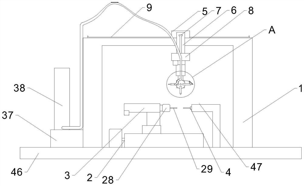
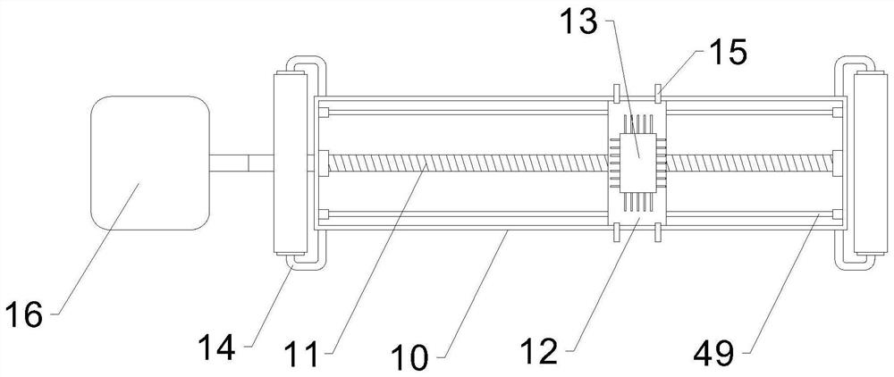
[0037] see Figure 1-8 Shown: a welding dispensing equipment for inductor production, including a first support frame 1, a coarse distance adjustment mechanism 2, a first fine distance adjustment mechanism 3, a clamping mechanism 4, a heater 37, a glue storage barrel 38, a support Platform 46 and the second fine distance adjustment mechanism 48, the upper side of the support platform 46 is equipped with a first support frame 1, and the upper side middle part of the support platform 46 is equipped with a coarse distance adju...


PUM


Abstract

The invention discloses welding and dispensing equipment for inductor production. The welding and dispensing equipment for inductor production comprises a first supporting frame, a coarse distance adjusting mechanism, a first fine distance adjusting mechanism, a clamping mechanism, a heater, a glue storage barrel and a second fine distance adjusting mechanism, the coarse distance adjusting mechanism comprises a cloth rolling mechanism, a distance adjusting box, a distance adjusting lead screw and a first motor, a fourth motor is installed on the lower side of the second fine distance adjusting mechanism, the fourth motor is fixedly connected with a supporting rotary disc, a glue dispenser and a spot welding machine are symmetrically installed on the other side face of the supporting rotary disc, a drying fan is installed between the glue dispenser and the spot welding machine, the heater is installed on one side of the first supporting frame, and the glue storage barrel is installed on the upper side of the heater. A heating wire prevents glue liquid in the glue storage barrel and an elastic hose from being solidified, the clamping force applied to each inductor is kept consistent, so that the inductors in the same batch are prevented from being excessively clamped due to the difference between individuals, the welding and dispensing quality of the inductors is greatly improved, and meanwhile, the energy utilization rate is improved.

Description

technical field [0001] The invention relates to the field of inductor production, in particular to a welding and dispensing device for inductor production and a method for using the same. Background technique [0002] An inductor is a component that can convert electrical energy into magnetic energy and store it. Its structure is similar to that of a transformer, but it has only one winding. It is generally composed of a skeleton, winding, shell, packaging material, magnetic core (or iron core), etc. The characteristics of the capacitor are just the opposite. It has the characteristics of preventing the passage of alternating current and allowing direct current to pass smoothly. It only hinders the change of current. If there is no current passing through, it will try to prevent the current from flowing through it when the circuit is turned on; When the current is flowing, it will try to maintain the current when the circuit is opened. [0003] When fixing the electromagnet...

Claims


Application Information

Patent Timeline
Patent Type & Authority Applications(China)
IPC IPC(8): B05C5/02B05C13/02B05C11/10B23K11/11B23K11/36B05C9/14B05D3/04
CPCB05C5/0208B05C13/02B05C11/1042B23K11/11B23K11/36B05C9/14B05D3/0413
Inventor 徐晓丽
Owner 深圳市三拓电子有限公司
Learn More