Ring-pull can shell cleaning device

A cleaning device and cans technology, which is applied in the directions of cleaning hollow objects, cleaning methods and utensils, chemical instruments and methods, etc., can solve the problems of difficult to clean and clean cans sewage, etc., and achieves the effect of convenient cleaning

Inactive Publication Date: 2021-06-04
马军义
View PDF6 Cites 2 Cited by
  • Summary
  • Abstract
  • Description
  • Claims
  • Application Information

AI Technical Summary

Problems solved by technology

[0005] In order to overcome the disadvantages of the existing methods of cleaning cans that require manual loading and manual cleaning of the cans one by one, making it difficult to clean and clean the sewage generated by th

Method used


Image

  • Ring-pull can shell cleaning device
  • Ring-pull can shell cleaning device
  • Ring-pull can shell cleaning device

Examples


Embodiment 1

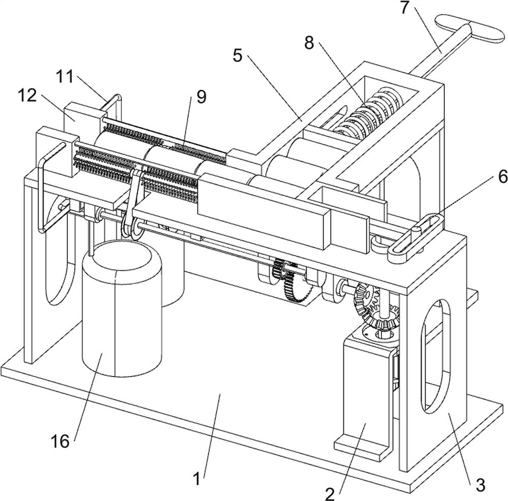
[0022] A kind of pop can shell cleaning device, such as figure 1 Shown, include base 1, motor seat 2, working platform 3, servo motor 4, waiting box 5, feeding mechanism 6, telescoping rod 7, return force spring 8, cleaning mechanism 9, cleaning bucket 10, water spray pipe 11 and Mounting base 12, base 1 top right side is provided with motor base 2, base 1 top is provided with work platform 3, and motor base 2 upper side is provided with servo motor 4, and the output shaft of servo motor 4 passes through motor base 2, and work platform 3 The rear side of the top is provided with a waiting box 5, and the right side of the top of the working platform 3 is provided with a feeding mechanism 6. The feeding mechanism 6 is connected with the output shaft of the servo motor 4, and the middle of the waiting box 5 is slidingly connected with a telescopic rod 7. 7 and the rear part of the inner wall of the material box 5 are connected with a return spring 8, and the return spring 8 is sl...

Embodiment 2

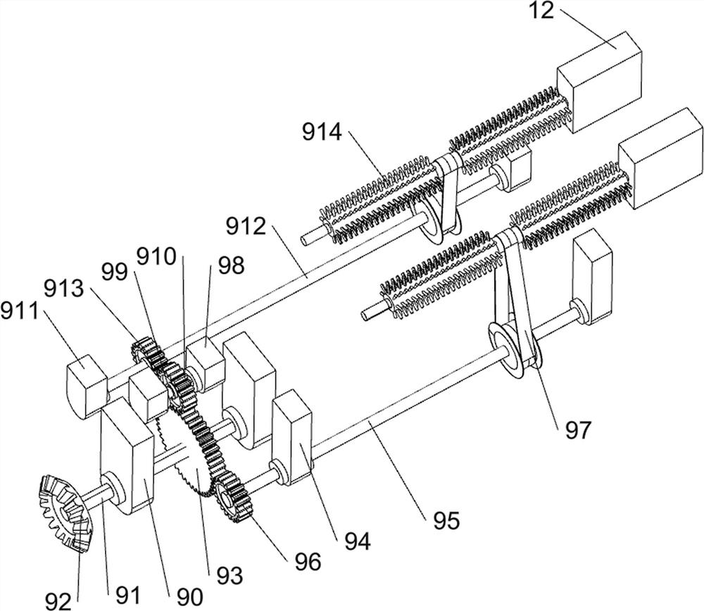
[0025] On the basis of Example 1, such as figure 2 and image 3 As shown, the feeding mechanism 6 includes a first rotating shaft 60, a first bevel gear 61, a rotating block 62, a push rod 63, a push plate 64, a baffle plate 65 and an annular guide rail 66, and the output shaft of the servo motor 4 is connected with the first rotating shaft 60, the first rotating shaft 60 passes through the working platform 3, the first bevel gear 61 is connected to the lower side of the first rotating shaft 60, the top of the first rotating shaft 60 is provided with a rotating block 62, and the middle part of the front side of the top of the working platform 3 is provided with a baffle 65, A push plate 64 is slidably connected between the baffle plate 65 rear portion and the front portion of the bin 5, the right portion of the push plate 64 is connected with a push rod 63, and the right portion of the push rod 63 is provided with an annular guide rail 66, and the annular guide rail 66 is con...

Embodiment 3

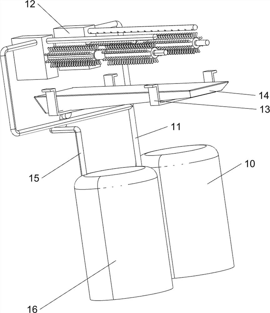
[0030] On the basis of Example 2, such as Figure 4 Shown, also include hanging plate 13, sewage collecting frame 14, sewage drain pipe 15 and sewage barrel 16, the left side of working platform 3 bottoms is evenly connected with hanging plate 13, the quantity of hanging plate 13 is 2, between hanging plate 13 Connected with a sewage collection frame 14, the sewage collection frame 14 is located below the brush 914, a sewage bucket 16 is arranged on the top front side of the right side of the base 1, and a sewage drainage pipe 15 is connected to the top of the sewage bucket 16, and the sewage drainage pipe 15 is connected to the sewage collection frame 14 Connected on the left.

[0031] When people need to collect and clean the sewage of the pop cans, under the cooperation of the cleaning bucket 10, the water spray pipe 11, the feeding mechanism 6 and the cleaning mechanism 9, the brush 914 cleans the shell of the pop can, and the water falls on the brush 914 to the brush. 91...


PUM


Abstract

The invention relates to a cleaning device, in particular to a ring-pull can shell cleaning device. According to the ring-pull can shell cleaning device, automatic feeding of ring-pull cans can be achieved, the ring-pull can shells can be automatically cleaned, and sewage can be conveniently collected. The ring-pull can shell cleaning device comprises a base and a motor base, wherein the motor base is arranged on the right side of the top of the base; a working platform which is arranged at the top of the base; a servo motor which is arranged on the upper side of the motor base; a material waiting box which is arranged on the rear side of the top of the working platform; a feeding mechanism which is arranged on the side, close to the servo motor, of the top of the working platform; a cleaning mechanism, wherein the left side of the top of the working platform is connected with a part of the cleaning mechanism; and a cleaning water bucket which is arranged on the side, far away from the motor base, of the base. By matching the servo motor, the feeding mechanism, the cleaning mechanism and a sewage collecting frame, ring-pull cans can be automatically fed, shells of the ring-pull cans can be automatically cleaned, and sewage generated after cleaning is conveniently collected.

Description

technical field [0001] The invention relates to a cleaning device, in particular to a cleaning device for pop can shells. Background technique [0002] Pop-top cans can be seen everywhere in people’s daily life. The development of pop-top cans has laid a solid foundation for the development of canning and beverage industries. In some areas where pop-top consumption is active, people begin to continuously increase the recycling of pop-top cans. Before recycling pop-top cans, it is generally necessary to The shell is cleaned. [0003] The existing method for cleaning the shell of pop cans is that people manually use a brush to clean the pop cans manually. People need to use the brush to clean the pop cans one by one. After the cleaning is completed, people also need to treat the cleaned sewage. The steps are complicated, and the cleaning efficiency of the shell of the can is low. [0004] Therefore need to research and develop a kind of pop can shell cleaning device that can...

Claims


Application Information

Patent Timeline
IPC IPC(8): B08B9/36B08B9/34B08B9/30B08B9/42
CPCB08B9/36B08B9/34B08B9/30B08B9/42
Inventor 马军义
Owner 马军义
Why Eureka
Try Eureka