Injection and blowing all-in-one machine with blowing groove

An all-in-one machine and bottle technology, applied in the field of plastic processing, can solve the problems of reducing processing efficiency, increasing equipment cost, affecting user experience, etc., so as to shorten the time of single processing, save the time of opening and closing molds, and improve space utilization. The effect of efficiency

Active Publication Date: 2021-06-04
ZHEJIANG HONGZHEN MASCH MOULD GRP CO LTD
View PDF6 Cites 0 Cited by
  • Summary
  • Abstract
  • Description
  • Claims
  • Application Information

AI Technical Summary

Problems solved by technology

During this process, the back-to-back translation distance of the side template needs to be greater than the diameter of the entire bottle body, resulting in an increase in the opening and closing distance of the side template, which not only needs to provide a larger operating space for the mold assembly, but also increases the size of the blowing mechanism , especially when setting multiple sets of mold components, it is necessary to reserve a larger running space, and it also increases the time required for a single opening and closing of the mold components, which reduces the processing efficiency, and the larger opening and closing distance of the side template needs to be increased Energy consumption affects the user experience, and it is necessary to set a driving structure for the side template to drive its opening and closing, which increases the cost of the equipment
[0005] In addition, the mold assembly can also be composed of a side plate and a bottom plate. When the mold is opened, the bottom plate translates laterally to expose the bottom of the mold cavity, so that the bottle body falls out of the mold cavity by free fall, resulting in an incompletely cooled and hardened bottle. Experience the collision with the side wall of the mold cavity due to the tilt of the posture during the free pot body process, causing the bottle body to be deformed or scratched by impact, which affects the quality and appearance of the bottle body

Method used


Image

  • Injection and blowing all-in-one machine with blowing groove
  • Injection and blowing all-in-one machine with blowing groove
  • Injection and blowing all-in-one machine with blowing groove

Examples


Embodiment 1

[0035] This embodiment provides an integrated injection and blowing machine with a blowing groove.

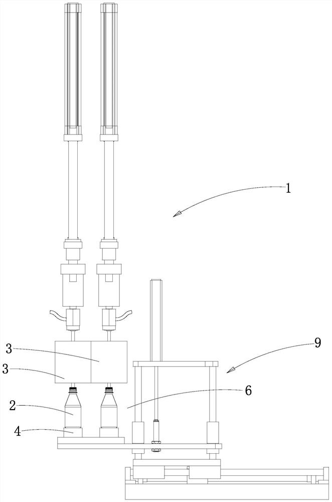
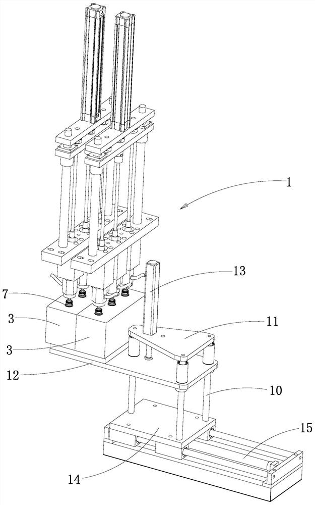
[0036] Such as figure 1 The injection blowing integrated machine shown is composed of an injection molding mechanism, a bottle blowing mechanism 1 and a transfer mechanism. The bottle blowing mechanism 1 receives the preform from the injection molding mechanism through the transfer mechanism and blows it to form a bottle body 2. The bottle blowing mechanism 1 includes The mold assembly that can enclose the mold cavity and the blow assembly that cooperates with the mold cavity, the bottle blank is put into the mold cavity and blown by the blow assembly to form the bottle body 2, it is characterized in that the mold assembly includes internal equipment The main mold body 3 of the blowing tank 5, the bottom template 4 arranged below the main mold body 3 and the stripping part arranged on the top of the main mold body 3, the bottom template 4 covers the groove of the blowing tank 5...

Embodiment 2

[0059] Compared with the first embodiment, this embodiment provides another specific structure of the injection-blowing integrated machine.

[0060] Such as Figure 5 As shown, there are two bottle blowing mechanisms 1 and they are arranged separately on both sides of the injection molding section, so that the preforms produced by the injection molding section are alternately transported to the corresponding bottle blowing mechanisms 1 by the transfer mechanism. In order to improve the processing efficiency, a bottle blowing mechanism 1 is respectively arranged on both sides of the injection molding part. Specifically, the injection molding part can form preforms by batch injection molding and supply them alternately to the bottle blowing mechanisms 1 on both sides, so that the bottle blowing mechanism 1 The bottle body 2 is blown by alternately receiving the preforms to increase the output of the bottle body 2 .

[0061] In this embodiment, the bottle blowing mechanism 1 inc...

Embodiment 3

[0064] Compared with the second embodiment, this embodiment provides another specific structure of the injection-blowing integrated machine.

[0065] Such as Figure 6 As shown, the driving member is a gripper 16, and the horizontal drive assembly includes a bottle-taking cylinder that drives the gripper 16 to reciprocate horizontally. The gripper 16 clamps the bottle body 2 and translates outward along the bottle-taking channel 6 driven by the bottle-taking cylinder. . When the bottle body 2 moves to the inner port of the bottle taking channel 6 with the bottom template 4, the gripper 16 moves along the bottle taking channel 6 driven by the bottle taking cylinder and retracts after grabbing the bottle body 2, so that the bottle body 2 moves along the bottle taking channel 6. Channel 6 breaks away from bottom template 4 . When the bottle body 2 is moved to the outer port of the bottle-taking channel 6, the clamp 16 releases the bottle body 2, so that the bottle body 2 falls ...


PUM


Abstract

The invention relates to an injection and blowing all-in-one machine with a blowing groove. An existing injection and blowing all-in-one machine is low in machining efficiency. The injection and blowing all-in-one machine with the blowing groove comprises an injection molding mechanism, a bottle blowing mechanism and a transfer mechanism, a bottle blank is placed in a mold cavity and blown by a blowing assembly to form a bottle body, a mold assembly comprises a main mold body, a bottom mold plate and a demolding piece, the bottom mold plate covers a groove opening of the blowing groove from bottom to top and defines the mold cavity, after blowing is completed, the demolding piece drives the bottle body to be vertically separated from the blowing groove, the bottom mold plate descends and supports the bottle body to synchronously move downwards, so that a bottle taking channel for the bottle body to horizontally move outwards is formed in the side part of the bottle body. The demolding piece is arranged on the main mold body, the demolding piece is used for driving the bottle body in the blowing groove to synchronously move downwards along with the bottom mold plate and be separated from the main mold body, a driving structure for opening and closing the blowing groove does not need to be arranged, the cost is reduced, the operation space needed by the mold assembly is effectively reduced, and the space utilization efficiency and the machining efficiency are effectively improved; and the bottle body quality and the bottle body attractiveness are ensured.

Description

technical field [0001] The invention relates to the field of plastic processing, in particular to an injection-blowing integrated machine. Background technique [0002] Existing injection-blow integrated machine includes injection molding mechanism, bottle blowing mechanism and transfer mechanism. The mold assembly and the blowing assembly matched with the mold cavity, the bottle blank is put into the mold cavity and blown by the blowing assembly to form a bottle body. [0003] During production, firstly, the raw material is heated in the injection molding mechanism and then injected to form a preform. Then, when the preform is not cooled and hardened, it is input into the blowing mechanism through the transfer mechanism. Finally, the blowing mechanism blows the received preform into a bottle body. Then send it out. [0004] Existing blow molding mechanism comprises mold assembly, after completing bottle body blowing, mold assembly is opened and is convenient to take out o...

Claims


Application Information

Patent Timeline
IPC IPC(8): B29C49/06B29C49/42
CPCB29C49/06B29C49/4205B29C2049/023
Inventor 蔡桂森蔡业
Owner ZHEJIANG HONGZHEN MASCH MOULD GRP CO LTD
Why Eureka
Try Eureka