Energy management method for hybrid electric vehicle

A technology for energy management and hybrid vehicles, applied to electric vehicles, hybrid vehicles, motor vehicles, etc., can solve problems such as increased switching frequency, increased vehicle fuel consumption, and worsened fuel economy, so as to reduce the frequency of switching back and forth and improve Battery life, the effect of reasonable and effective energy management

Active Publication Date: 2021-06-04
上海新动力汽车科技股份有限公司
View PDF4 Cites 0 Cited by
  • Summary
  • Abstract
  • Description
  • Claims
  • Application Information

AI Technical Summary

Problems solved by technology

[0004] The existing technology mainly uses fixed values ​​as the SOC upper and lower thresholds to constrain the SOC. However, due to the strong followability of the fluctuation range of the battery power with temperature changes, it cannot flexibly respond to changes in battery capacity under various ambient temperatures, which is not conducive to the realization of Reasonable and effective hybrid vehicle energy management
When the ambient temperature drops, the battery capacity will decrease accordingly, resulting in a significant increase in the power mode switching frequency of the hybrid vehicle compared with the normal ambient temperature, thereby deteriorating fuel economy and shortening battery life
In addition, if the torque demand of hybrid vehicles fluctuates frequently, it will also cause frequent switching of power modes, which will seriously affect the driving experience and increase the fuel consumption of the vehicle.

Method used


Image

  • Energy management method for hybrid electric vehicle
  • Energy management method for hybrid electric vehicle
  • Energy management method for hybrid electric vehicle

Examples


Embodiment Construction

[0041] The present invention will be further described below in conjunction with specific examples.

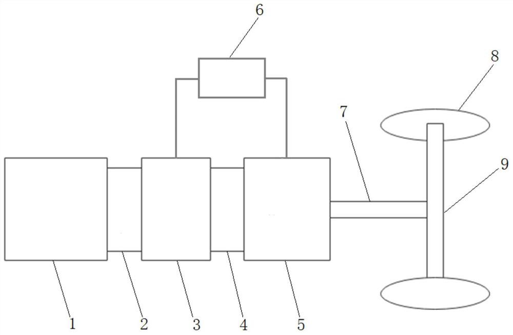
[0042] see figure 1 , an energy management method for a hybrid vehicle, the hybrid vehicle includes an engine 1 , a first clutch 2 , an ISG motor 3 , a second clutch 4 , a TM motor 5 and a battery 6 . The engine 1, the first clutch 2, the ISG motor 3, the second clutch 4, and the TM motor 5 are connected in sequence, the battery 6 is respectively connected to the ISG motor 3 and the TM motor 5 through the motor controller, and the output end of the TM motor 5 is connected to the transmission shaft 7, Transmission shaft 7 is connected with transmission bridge 9, and wheel 8 is arranged at the end of transmission bridge 9.

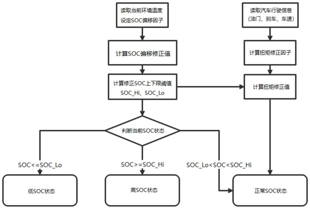
[0043] see figure 2 , the energy management method, comprising the steps of:

[0044] Step 1, read the current ambient temperature through the CAN message; set the SOC offset factor, and calculate the SOC offset correction value; set the calibrated SOC u...


PUM


Abstract

The invention relates to an energy management method for a hybrid electric vehicle. The energy management method sequentially comprises the following steps of reading the current environment temperature; setting an SOC offset factor, and obtaining an SOC offset correction value through calculation; setting a calibrated SOC upper limit threshold value and a calibrated SOC lower limit threshold value, and calculating to obtain a corrected SOC upper limit threshold value and a corrected SOC lower limit threshold value; reading current accelerator, brake and vehicle speed information; calculating to obtain a torque correction factor; establishing a mathematical model of the torque correction factor, the SOC and the torque correction value; if the current SOC is smaller than or equal to the corrected SOC lower limit threshold value, making the automobile enter a low SOC state, and making the engine output power; if the current SOC is larger than or equal to the corrected SOC upper limit threshold value, making the automobile enter a high SOC state, and making the TM motor output power; and if the current SOC is larger than the corrected SOC lower limit threshold value and smaller than the corrected SOC upper limit threshold value, making the automobile enter a normal SOC state, and the engine, the TM motor and the ISG motor are in series-parallel connection to output power. According to the method, the electric quantity of the battery can be stabilized in a reasonable working interval, and the power mode switching frequency is reduced.

Description

technical field [0001] The invention relates to energy management of a hybrid electric vehicle, in particular to an energy management method suitable for a dual-motor dual-clutch hybrid electric vehicle. Background technique [0002] The power system of a hybrid electric vehicle (referred to as a hybrid vehicle) includes an engine drive system and a motor drive system. The power required for driving a hybrid vehicle can be provided independently by a single drive system or jointly provided by two drive systems. The battery is an important part of the motor drive system. The battery can be used as the energy source of the motor drive system to output electric energy, and it can also be used to store the electric energy generated when the motor is in charging mode. Therefore, the charging of the battery in the vehicle system State (i.e. SOC) is the key point of hybrid vehicle energy management. [0003] Usually, see figure 1 , in a hybrid vehicle, the engine 1, the first clu...

Claims


Application Information

Patent Timeline
Patent Type & Authority Applications(China)
IPC IPC(8): B60W10/26B60W10/08B60W10/06B60W20/13B60L58/12
CPCB60W10/26B60W10/08B60W10/06B60W20/13B60L58/12B60W2510/244B60W2710/0666B60W2710/083B60W2510/0638Y02T10/70Y02T10/62
Inventor 陆鹏程李振华戴文豪张卫鑫陈劲松纪丽伟凌建群
Owner 上海新动力汽车科技股份有限公司
Why Eureka
Try Eureka