
Giant-span underground cave depot reserved double-rock-pillar support eight-part excavation construction method

A construction method and cavern technology, applied in underground chambers, earthwork drilling, wellbore lining, etc., can solve the problems of no technical standard construction technology, no successful case projects, and high economic costs, so as to achieve spacious construction space and ensure surrounding rock stability and high operating efficiency

Pending Publication Date: 2021-06-04
CHINA RAILWAY TUNNEL GROUP CO LTD +2
View PDF5 Cites 0 Cited by
  • Summary
  • Abstract
  • Description
  • Claims
  • Application Information

AI Technical Summary

Problems solved by technology

However, due to the small size of each block, after each excavation part is excavated, the temporary support is followed up in time to stabilize the deformation of the surrounding rock. After all the excavation parts are excavated and supported, the temporary support is removed, which can effectively Control the deformation of the surrounding rock to ensure the stability of the surrounding rock and construction safety, but the project progress is slow and the economic cost is high. How to achieve the best compromise between safety and economy is the key to the long-span underground cavern project under complex stratum conditions. The starting point of block form and size is to minimize the construction cost on the premise of ensuring construction safety as much as possible
[0004] For the construction of giant-span underground caverns with a span of more than 70m under the condition of hard rock formation, there is no successful case project in China at present, and there is no corresponding technical standard and mature construction technology

Method used


Image

  • Giant-span underground cave depot reserved double-rock-pillar support eight-part excavation construction method
  • Giant-span underground cave depot reserved double-rock-pillar support eight-part excavation construction method

Examples


Embodiment Construction

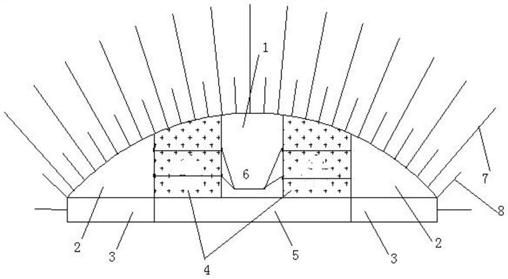
[0028] The present invention is an excavation construction method for eight sections supported by double rock pillars reserved for giant-span underground caverns, which is suitable for giant-span underground cavern projects with hard surrounding rock formations spanning more than 70m but less than 75m, and the surrounding rock level belongs to Class II Or level III, that is, [BQ] between 400 and 550; applicable cavern section form: straight wall arched flat razor-shaped section without inversion, side wall height not exceeding 10m, and sagittal height not exceeding 10m; the groundwater level is required to be Below the cavern floor.

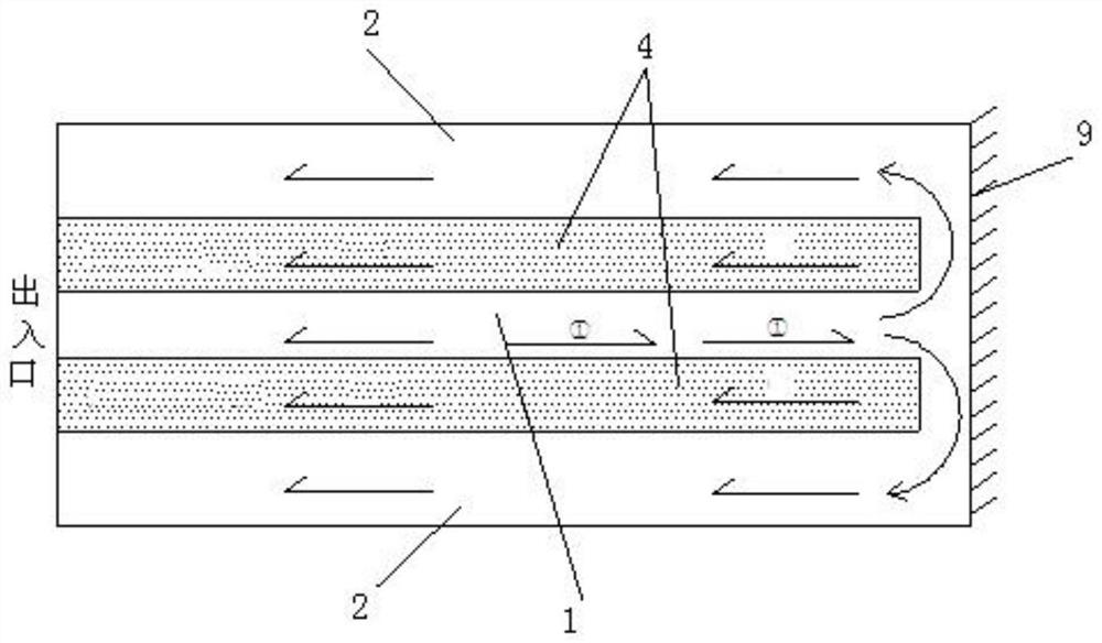
[0029] During construction, the excavation surface of the cavern shall be partitioned first, such as figure 1 with figure 2 As shown in , the excavation surface of the cavern is divided vertically into two separate upper and lower parts, the part above the arch line is the upper part construction area, and the part below is the lower part const...


PUM


Abstract

The invention discloses a reserved double-rock-pillar support eight-part excavation construction method for a huge-span underground cave depot, which comprises the following steps: 1, dividing an excavation surface of the cave depot into an upper part and a lower part which are independent from each other in the vertical direction, taking the part above an arch camber line as an upper part construction area, and taking the part below the arch camber line as a lower part construction area; 2, excavating the first part in a full-section mode till the front end wall is reached; 3, excavating transverse channels towards the left side and the right side at the front end wall of the first part till the second part area is reached; 4, in the two second part areas on the left side and the right side, excavating pilot tunnels backwards in the reverse direction from the tunnel face till the tunnels go out of the tunnel. 5, excavating the third part at the bottom till the front end wall is reached; 6, excavating fourth parts on the left side and the right side in a staggered mode till the front end wall; and 7, excavating the fifth part till the position of the front end wall. According to the construction method, original surrounding rock masses are fully utilized to replace manual materials to serve as temporary supports of the cave depot, and the material cost is saved.

Description

technical field [0001] The invention belongs to the technical field, and in particular relates to an excavation construction method for eight sections supported by double rock pillars reserved for a giant-span underground cavern. Background technique [0002] For the long-span underground cavern project in hard rock formation, when the span does not exceed 40m, the relatively mature half-section method and step method can be selected according to factors such as surrounding rock formation conditions, cavern span size, mechanical equipment technical level, and surrounding environment. , Double-side wall pilot pit method, single rock pillar support divisional excavation method and other construction methods, these methods are relatively mature at present, and have formed technical standards and specifications. Firstly, according to the geological survey results, determine the RQD value of the stratum, and determine the grade of the surrounding rock, and then preliminarily dete...

Claims


Application Information

Patent Timeline
IPC IPC(8): E21D9/00E21D11/00E21D11/10
CPCE21D9/00E21D11/006E21D11/10
Inventor 杨朝帅刘永胜卓越姚士磊林春刚邵阳熊炎林种玉配杨效广安博金星亮代昱昊尚伟
Owner CHINA RAILWAY TUNNEL GROUP CO LTD
Features
  • Generate Ideas
  • Intellectual Property
  • Life Sciences
  • Materials
  • Tech Scout
  • Unparalleled Data Quality
  • Higher Quality Content
  • 60% Fewer Hallucinations
Learn More