Speed change mechanism capable of realizing large-range regulation and control and used for machining

A technology of mechanical processing and speed change mechanism, which is applied in the direction of mechanical equipment, components with teeth, transmission device control, etc., can solve the problems of reduced speed change accuracy, insufficient stability and range of speed change, stroke rebound, etc., and achieve improvement Accuracy and Stability, Improve Stability and Accuracy, Improve Efficiency

Pending Publication Date: 2021-06-04
孙萱泽
View PDF0 Cites 2 Cited by
  • Summary
  • Abstract
  • Description
  • Claims
  • Application Information

AI Technical Summary

Problems solved by technology

[0003] However, most of the existing speed change mechanisms are adjusted by the cylinder. Although the cylinder adjustment can perform a certain degree of speed change operation, its stability and the range of speed change are insufficient, and the stroke of the cylinder may return air when changing speed. , which in turn causes stroke rebound and reduces the accuracy of subsequent shifting. Therefore, there is an urgent need for a shifting mechanism for machining that can be adjusted in a wide range to solve the above-mentioned problems.

Method used


Image

  • Speed change mechanism capable of realizing large-range regulation and control and used for machining
  • Speed change mechanism capable of realizing large-range regulation and control and used for machining
  • Speed change mechanism capable of realizing large-range regulation and control and used for machining

Examples


Embodiment Construction

[0027] The following will clearly and completely describe the technical solutions in the embodiments of the present invention with reference to the accompanying drawings in the embodiments of the present invention. Obviously, the described embodiments are only some, not all, embodiments of the present invention. Based on the embodiments of the present invention, all other embodiments obtained by persons of ordinary skill in the art without making creative efforts belong to the protection scope of the present invention.

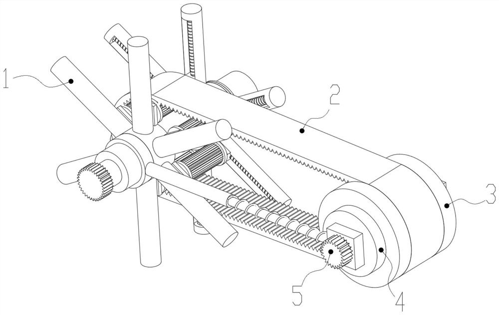
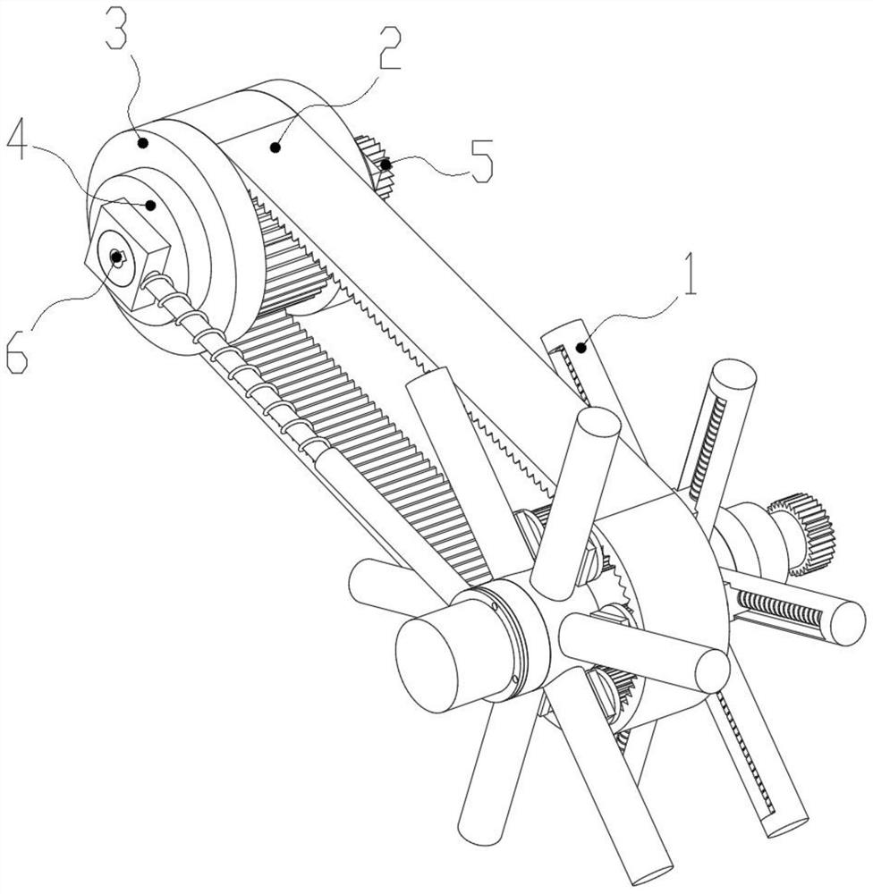
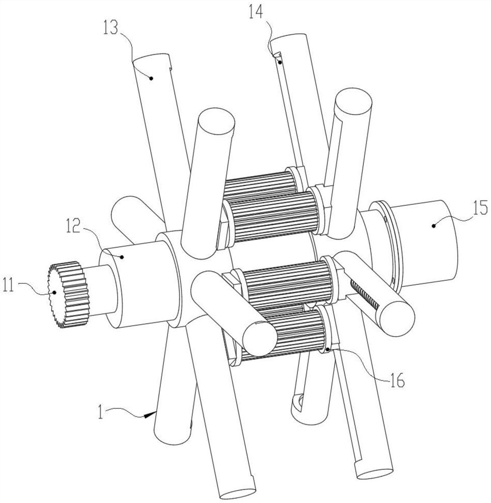
[0028] see Figure 1-8 , an embodiment provided by the present invention: a speed change mechanism for machining that can be adjusted in a wide range, including an adjustment mechanism 1, a toothed belt 2, a toothed pulley 3, a limit mechanism 4, a transmission gear 5 and a plug-in slot 6,

[0029] The outer end surface of the adjustment mechanism 1 is connected with a limit mechanism 4 for support in symmetrical rotation, and the inner end surface of the two...


PUM


Abstract

The invention discloses a speed change mechanism capable of realizing large-range regulation and control and used for machining. The speed change mechanism comprises an adjusting mechanism, a tooth-shaped belt, a tooth-shaped belt wheel, limiting mechanisms, a transmission gear and an inserting groove, and the limiting mechanisms used for supporting are symmetrically and rotationally clamped to the outer end surface of the adjusting mechanism. The adjusting mechanism is arranged, when speed change is carried out, a gear rotating plate and guide gears are arranged, so that when the gear rotating plate rotates, power can be uniformly conveyed to the six sets of guide gears, and then the guide gears can drive a threaded shaft to rotate through connecting supporting rods; a positioning sliding block is arranged at the outer part of the threaded shaft in a threaded mode, through the threaded displacement mode, the accuracy and stability of displacement of the positioning sliding block outside the threaded shaft can be effectively improved, after the radius of the positioning belt wheel is adjusted, the transmission stability and accuracy can be improved to the maximum degree, and thus the follow-up speed change efficiency is improved.

Description

technical field [0001] The invention relates to the technical field of mechanical equipment, in particular to a speed change mechanism for machining that can be adjusted in a wide range. Background technique [0002] The speed change mechanism for machining is a mechanism used to change the speed and torque from the engine. It can quickly change the transmission ratio of the output shaft and the input shaft, so as to meet the needs of processing machinery for different speeds and improve the speed of subsequent processing machinery for workpieces. stable processing, [0003] However, most of the existing speed change mechanisms are adjusted by the cylinder. Although the cylinder adjustment can perform a certain degree of speed change operation, its stability and the range of speed change are insufficient, and the stroke of the cylinder may return air when changing speed. , which in turn causes stroke rebound and reduces the accuracy of subsequent gear shifting. Therefore, t...

Claims


Application Information

Patent Timeline
Patent Type & Authority Applications(China)
IPC IPC(8): F16H9/24F16H55/54F16H61/32F16H61/662
CPCF16H9/24F16H55/54F16H61/32F16H61/662F16H2061/2884F16H2061/66295
Inventor 孙萱泽
Owner 孙萱泽
Why Eureka
Try Eureka