Valve impact performance test pipeline and system

A technology for impact performance and pipeline testing, which is applied in mechanical valve testing and other directions, and can solve problems such as pipeline volume changes and difficult detection

Pending Publication Date: 2021-06-04
XIAN AEROSPACE PROPULSION INST
View PDF9 Cites 0 Cited by
  • Summary
  • Abstract
  • Description
  • Claims
  • Application Information

AI Technical Summary

Problems solved by technology

[0003] The purpose of the present invention is to provide a valve impact performance testing pipeline and system to solve the probl

Method used


Image

  • Valve impact performance test pipeline and system
  • Valve impact performance test pipeline and system
  • Valve impact performance test pipeline and system

Examples


Embodiment 1

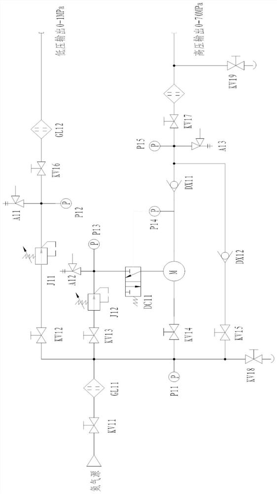
[0055] In this embodiment, a pipeline for testing the impact performance of a pressure reducing valve is disclosed, such as figure 2 , 6 , 7, 8, the present embodiment figure 2 , 6 , 7, and 8 are spliced ​​in sequence to form the impact performance test pipeline of the pressure reducing valve. On the basis of the above-mentioned embodiments, the following technical features are also disclosed:

[0056] The inlet of the gas pressurization pipeline is connected to the gas source through a cut-off valve KV11 and a filter GL11, and the filter GL11 is connected with a first pressurization branch pipe, a second pressurization branch pipe, a second pressurization branch pipe, and a second pressurization branch pipe. The third booster branch and the fourth booster branch,

[0057] The first pressurization branch pipe is connected in turn with a stop valve KV12, a manual pressure reducing valve J11, a pressure gauge P12, a stop valve KV16 and a filter GL12. The pressure gauge P12 ...


PUM


Abstract

The invention belongs to the technical field of valve tests, and discloses a valve impact performance test pipeline and system. The system comprises a mechanical system and a measurement and control system, the mechanical system is used for providing a gas medium and working conditions for a tested piece, and the measurement and control system is used for controlling the gas medium and the working conditions and automatically collecting and storing test parameters. The mechanical system comprises a gas pressurizing unit, a high-pressure gas cylinder unit, a pressure reducing valve mounting unit, a gas cushion simulation unit and a flow adjusting unit; the gas pressurizing unit is used for pressurizing a gas medium; the high-pressure gas cylinder unit is used for storing and releasing a gas medium; the pressure reducing valve mounting unit is used for clamping and fixing a tested valve; the air cushion simulation unit is used for simulating the volume change of a pipeline behind the tested valve; the flow simulation unit is used for simulating working conditions when the valve flows are different.

Description

technical field [0001] The invention belongs to the technical field of valve testing, and in particular relates to a valve impact performance testing pipeline and system. Background technique [0002] In the conventional valve test system, the usual way to adjust the volume of the cavity after the test piece is: fill the water tank with water, control the water filling volume of the water tank, and use the remaining volume in the water tank as the simulated air cushion volume. The disadvantages of this method are: : 1) The system needs to increase the water medium subsystem, and the water supply and drainage of the container need to be considered, and the system is relatively complicated; 2) The volume control is realized by liquid level control, and the accuracy is low; 3) The follow-up pipeline of the simulated air cushion has a Larger water vapor has come, affecting the accuracy and life of the system, causing potential safety hazards; 4) The volume occupied is relatively...

Claims


Application Information

Patent Timeline
IPC IPC(8): G01M13/003
CPCG01M13/003
Inventor 刘中华张文娇李海刘国栋陈锦韩流钟伟锋
Owner XIAN AEROSPACE PROPULSION INST
Why Eureka
Try Eureka