Braking device and method for automobile crash test

A technology of crash test and braking device, applied in the field of automobile crash test, can solve the problems of complicated installation and maintenance, large volume and high overall price, and achieve the effect of reducing test loss, small size and good versatility

Pending Publication Date: 2021-06-04
CHONGQING CHANGAN AUTOMOBILE CO LTD
View PDF7 Cites 0 Cited by
  • Summary
  • Abstract
  • Description
  • Claims
  • Application Information

AI Technical Summary

Problems solved by technology

Hydraulic cylinders or pneumatic cylinders can be conveniently set to adjust the time-deceleration curve, but the hydraulic cylinder / pneumatic cylinder braking device requires oil pumps, oil cylinders, air pumps and other supporting equipment, the overall price is high, the volume is large, and the installation and maintenance are complicated

Method used


Image

  • Braking device and method for automobile crash test
  • Braking device and method for automobile crash test
  • Braking device and method for automobile crash test

Examples


Embodiment 1

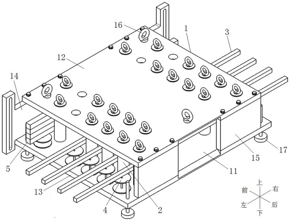
[0035] Embodiment one, see Figure 3 to Figure 7 , the brake device shown for the automobile crash test includes a housing 1, a plurality of limiting column units 2 arranged at intervals along the front-rear direction in the housing, and energy-absorbing rods 3 corresponding to the limiting column units 2. The casing 1 runs through from left to right, and includes a front plate body 14 , an upper plate body 12 , a rear plate body 15 and a lower plate body 13 connected in sequence.

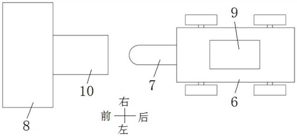
[0036] The rear plate body 15 of the housing 1 is provided with an opening 11 corresponding to the collision nose 7 at the front end of the tractor 6 . Due to the slight vibration during the operation of the tractor 6, the collision nose 7 jumps up and down, and a chamfer is provided at the opening 11 of the housing 1. When the collision nose 7 hits the housing 1 due to the up and down jump, the chamfer can guide the collision nose Correctly enter the braking device, protect the braking device and...

Embodiment 2

[0043] Embodiment 2, using the seat system as the component to be tested, and using ECER44 as the test regulation to carry out the crash test, specifically includes the following steps:

[0044] Step 1, CAE simulation determines the braking device parameters.

[0045] 1) see figure 1 Establish a CAE model, the CAE model includes a flatbed tractor 6, a collision nose and a braking device for an automobile collision test,

[0046] 2) Set the speed of tractor 6 to 49±1km / h;

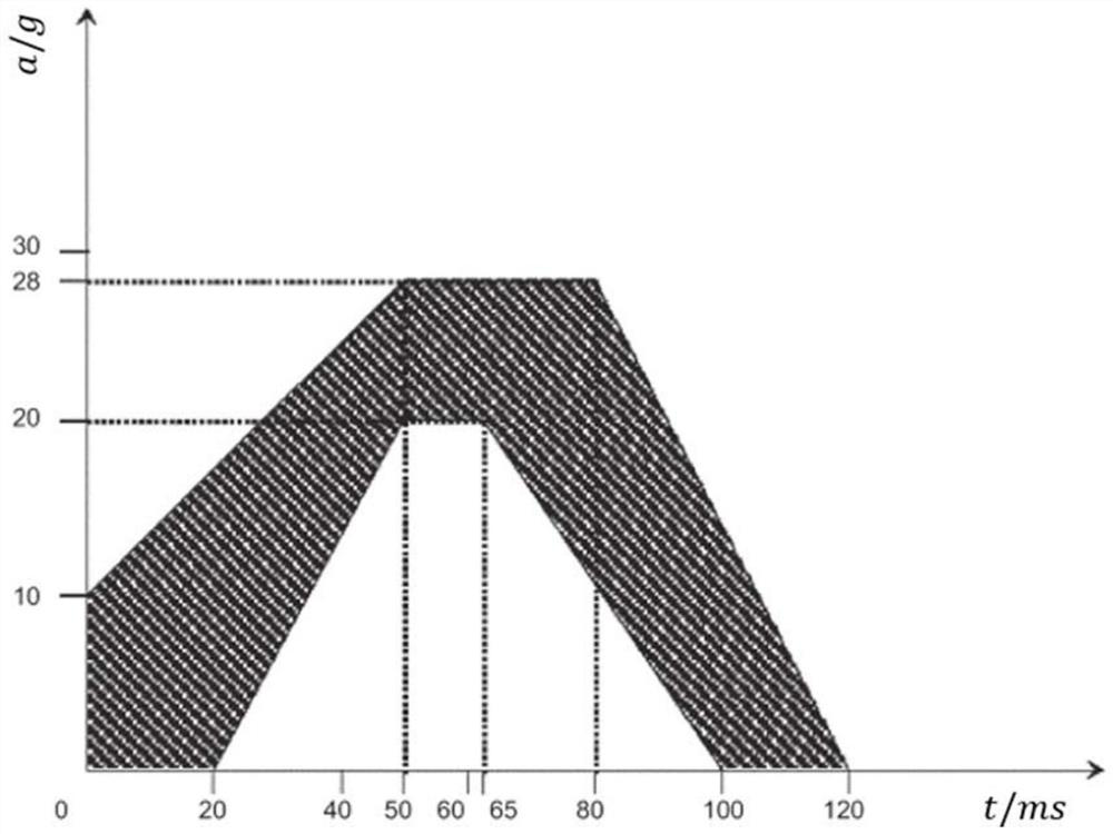
[0047] 3) The tractor 6 runs at a set speed until the collision nose 7 rushes into the braking device, and the collision nose 7 forces the energy-absorbing rod 3 to plastically deform to absorb the kinetic energy of the tractor 6 . The parameters of the braking device are determined through CAE simulation so that the tractor 6 can realize the time-deceleration curve stipulated by regulations. The braking device parameters include:

[0048] Four energy-absorbing rods 3 with a length of 2000mm and a radial...


PUM


Abstract

The invention discloses a braking device and method for an automobile crash test, and the device comprises a housing, and a limiting column unit and an energy absorption rod which are arranged in the housing at an interval along the front-back direction, and the rear side wall of the housing is provided with an opening which is correspondingly matched with a crash nose at the front end of a tractor; each limiting column unit comprises a front first limiting column and a rear second limiting column, the first limiting columns and the second limiting columns are vertically arranged, the first limiting columns are symmetrically arranged along the axis of the opening, the axes of the first limiting columns are located on the same plane, the second limiting columns are symmetrically arranged along the axis of the opening, and the axes of the second limiting columns are located on the same plane, the distance between the two first limiting columns close to the axis of the opening is smaller than the distance between the two second limiting columns close to the axis of the opening, the energy-absorbing rod is transversely inserted into a gap between the first limiting column and the second limiting column, and the two ends of the energy-absorbing rod extend out of the shell. The structure is simple, the time-deceleration curve requirements of different laws and regulations can be met by adjusting the arrangement parameters of the energy absorption rods, and the universality is good.

Description

technical field [0001] The invention relates to an automobile collision test, in particular to a braking device and method for the automobile collision test. Background technique [0002] In vehicle technology development, a crash test device that simulates a vehicle crash state is used to observe the condition and load of the occupant at the time of a vehicle crash, thereby evaluating the safety of the vehicle. For example, the car seat system needs to meet various test regulations, such as GB15083, GB13057, GB14167, ECER16, ECER17, ECER44, FMWSS213, etc. These regulations all include similar forms of crash safety tests to test the safety of the seat system under crash conditions sex. Taking ECER44 as an example to introduce the test requirements, see figure 1 , the seat system is fixed on the flat tractor 6 by frock 9, and the front end of the flat tractor 6 is equipped with a collision nose 7. An existing braking device 10 is fastened in front of the base wall 8 . The...

Claims


Application Information

Patent Timeline
Patent Type & Authority Applications(China)
IPC IPC(8): G01M17/007G01M7/08
CPCG01M17/0078G01M7/08
Inventor 谭侃伦王健唐倬马敏
Owner CHONGQING CHANGAN AUTOMOBILE CO LTD
Why Eureka
Try Eureka