Radar radiation source identification method based on multistage jumper residual network

A recognition method and radiation source technology, which are applied in the recognition of patterns in signals, neural learning methods, character and pattern recognition, etc., can solve problems such as the need to improve the recognition performance, increase the number of network layers, and the disaster of dimensionality, and achieve subtle features. Excellent extraction ability, improve efficiency, and suppress the effect of cross terms

Pending Publication Date: 2021-06-04
中国人民解放军海军航空大学航空作战勤务学院
View PDF4 Cites 2 Cited by
  • Summary
  • Abstract
  • Description
  • Claims
  • Application Information

AI Technical Summary

Problems solved by technology

[0003] In recent years, the feature extraction method based on machine learning has greatly improved the effect compared with the traditional algorithm, but there are still the following deficiencies: first, because the characteristics of the signal itself are not fully considered, it is easy to cause feature loss; second, the current Some deep feature learning capabilities and recognition performance under low signal-to-noise ratio need to be improved; third, due to the excessive input features of the neural network, the number of network layers continues to increase, resulting in the "dimension disaster"

Method used


Image

  • Radar radiation source identification method based on multistage jumper residual network
  • Radar radiation source identification method based on multistage jumper residual network
  • Radar radiation source identification method based on multistage jumper residual network

Examples


Embodiment Construction

[0055] The technical solutions of the present invention will be further specifically described below through the embodiments and in conjunction with the accompanying drawings. In the specification, the same or similar reference numerals designate the same or similar components. The following description of the embodiments of the present invention with reference to the accompanying drawings is intended to explain the general inventive concept of the present invention, but should not be construed as a limitation of the present invention.

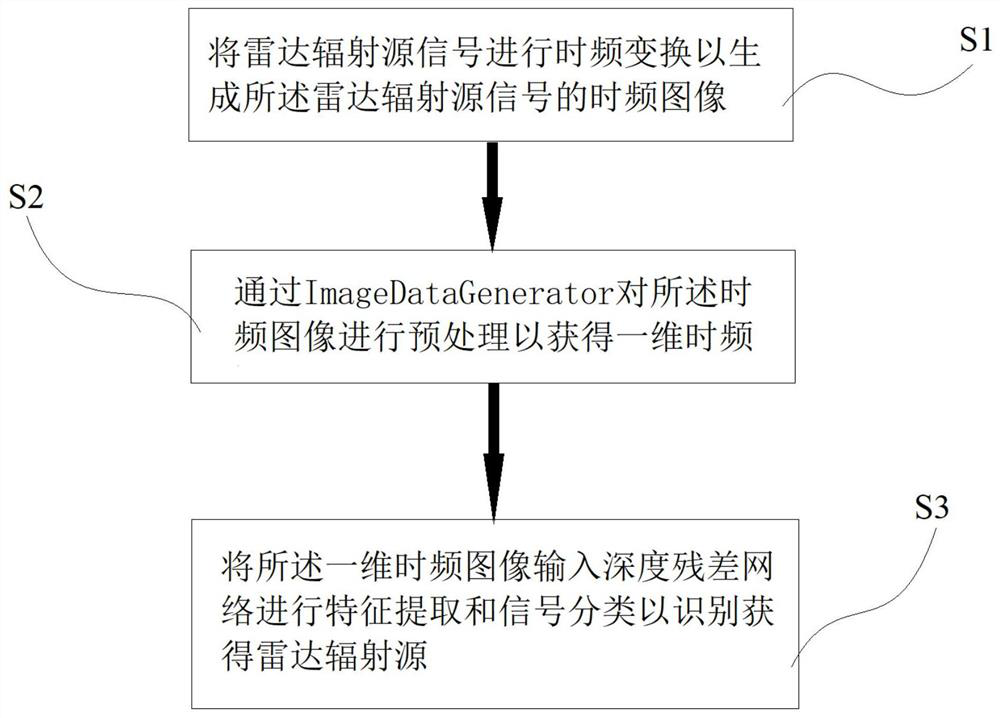
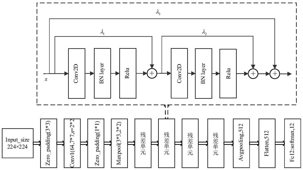
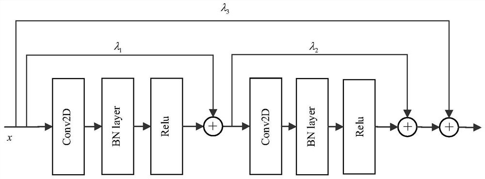
[0056] see figure 1 , which shows the flow of a radar emitter identification method based on a multi-level jumper residual network according to an embodiment of the present invention. The present invention proposes a deep residual network based on time-frequency feature extraction. First, smooth pseudo-Wigner-Ville time-frequency transformation is performed on the radiation source signal to generate a time-frequency image. After preprocessing,...


PUM


Abstract

The invention discloses a radar radiation source identification method based on a multistage jumper residual network, and belongs to the field of image processing. The radar radiation source identification method comprises the following steps: performing time-frequency transformation on a radar radiation source signal to generate a time-frequency image of the radar radiation source signal; carrying out the preprocessing of the time frequency image through an ImageDataGenerator, so as to obtain a one-dimensional time frequency image; and inputting the one-dimensional time-frequency image into a deep residual network for feature extraction and signal classification so as to identify and obtain the radar radiation source. According to the radar radiation source identification method based on the multistage jumper residual network provided by the invention, eight sequentially connected residual blocks are arranged in a deep residual network and are connected by using jumpers to form four residual units, so that the constructed deep residual network with the total convolution layer number of 18 can extract deep information of a signal time-frequency image, and meanwhile, the problems of gradient disappearance, gradient explosion and the like of the network are also avoided.

Description

technical field [0001] The invention relates to the field of image processing, in particular to a radar radiation source identification method based on a multi-level jumper residual network. Background technique [0002] With the rapid development of artificial intelligence technology in recent years, the intelligent processing of radar signals has become an important development trend. Deep learning has made breakthroughs in image classification, computer vision and language processing due to its advantages of automatic feature extraction and strong model generalization. [0003] In recent years, the feature extraction method based on machine learning has greatly improved the effect compared with the traditional algorithm, but there are still the following deficiencies: first, because the characteristics of the signal itself are not fully considered, it is easy to cause feature loss; second, the current Some deep feature learning capabilities and recognition performance un...

Claims


Application Information

Patent Timeline
Patent Type & Authority Applications(China)
IPC IPC(8): G06K9/00G06K9/62G06N3/04G06N3/08
CPCG06N3/08G06N3/084G06N3/045G06F2218/02G06F2218/08G06F2218/12G06F18/241G06F18/214
Inventor 闫文君谭凯文凌青张立民张兵强徐涛方君
Owner 中国人民解放军海军航空大学航空作战勤务学院
Why Eureka
Try Eureka