Interference positioning method, interference positioning device and distributed base station system

A technology of a base station system and a positioning method, applied in the field of communication, can solve the problems of high instrument cost, low efficiency, time-consuming interference positioning, etc., and achieve the effects of practical engineering, simple maintenance, and reduced engineering maintenance costs.

Active Publication Date: 2021-06-04
DATANG MOBILE COMM EQUIP CO LTD
View PDF10 Cites 3 Cited by
  • Summary
  • Abstract
  • Description
  • Claims
  • Application Information

AI Technical Summary

Problems solved by technology

[0005] The embodiment of the present application provides an interference location method to solve the problems of time-consuming, in

Method used


Image

  • Interference positioning method, interference positioning device and distributed base station system
  • Interference positioning method, interference positioning device and distributed base station system
  • Interference positioning method, interference positioning device and distributed base station system

Examples


Embodiment 1

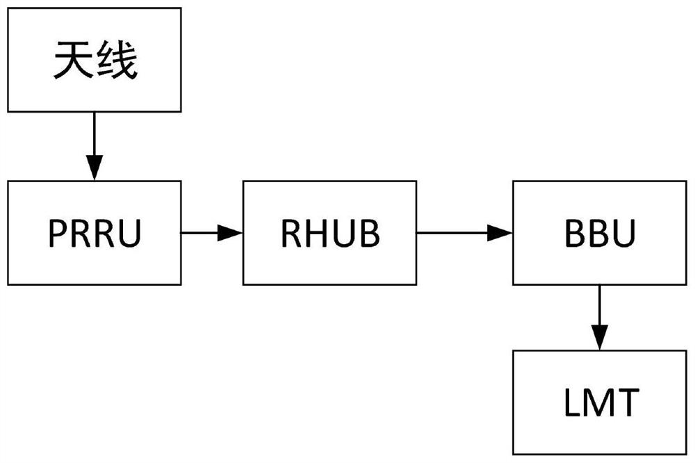
[0106] refer to Figure 4 , shows a flow chart of the steps of Embodiment 1 of an interference location method of the present application. This embodiment can be applied in a BBU (Base Band Unit, baseband processing unit) in a base station system, and the base station system communicates with local maintenance Terminal LMTs are connected.

[0107] The embodiment of the present application may specifically include the following steps:

[0108] Step 401, obtaining 5G air interface data in the current network scene;

[0109] Among them, the current network scene refers to the scene where information is exchanged between the current base station system and the mobile terminal; 5G air interface data refers to the 5G information data obtained through the new air interface.

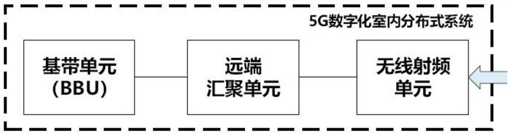
[0110] As an example, the current network scenario may include a distributed base station system deployed in an underground parking lot and mobile terminals used for networking in the parking lot.

[0111] In...

Embodiment 2

[0130] refer to Figure 5 , shows a flow chart of the steps of Embodiment 2 of an interference location method of the present application, and the method is applied in a BBU (Base Band Unit, baseband processing unit) in a base station system.

[0131] Specifically, the following steps may be included:

[0132] Step 501, obtaining 5G air interface data in the current network scene;

[0133] In an embodiment of the present application, step 501 may include the following sub-steps:

[0134] S5011. Turn on the NR air interface listening mode; in the NR air interface listening mode, acquire 5G air interface data when information is exchanged between the base station system and the mobile terminal.

[0135] In the specific implementation, the NR air interface listening mode can be turned on when performing interference positioning. In the NR air interface listening mode, the 5G air interface data of the current network scene can be obtained through the NR air interface, and the NR...


PUM


Abstract

The embodiment of the invention provides an interference positioning method, an interference positioning device and a distributed base station system. The method is applied to a baseband processing unit (BBU) in the base station system, and the base station system is connected with a local maintenance terminal (LMT) through a network cable. The method comprises the following steps: acquiring 5G air interface data in a current network scene; performing spectrum analysis on the 5G air interface data to obtain spectrum analysis data; performing parameter calculation on the spectrum analysis data to obtain spectrum parameters; transmitting the frequency spectrum parameter to an LMT, wherein the LMT is used for generating an LMT curve spectrogram according to the spectrum parameters and displaying the LMT curve spectrogram; and determining an interference signal according to the LMT curve spectrogram. By acquiring the 5G air interface data in the current network scene in the base station system, performing spectrum analysis, and performing parameter calculation on the spectrum analysis data, the interference signal positioning is simpler, the engineering is more practical, a special interference frequency sweeping instrument is omitted, and the engineering maintenance cost and the network optimization cost are reduced.

Description

technical field [0001] The present application relates to the technical field of communications, and in particular to an interference locating method, an interference locating device, and a distributed base station system. Background technique [0002] With the development of the fifth generation of mobile communication, with the characteristics of high bandwidth, high reliability, low delay, and massive connections, 5G (5th generation mobile networks or 5th generation wireless systems or 5th-Generation, fifth-generation mobile communication technology) applications The scope goes far beyond the traditional communication and mobile Internet, and expands to various industries and fields in an all-round way. Typical application scenarios of 5G include automatic driving, remote control, VR (Virtual Reality, virtual reality technology) / AR (Augmented Reality, augmented reality technology), smart manufacturing, smart grid, etc., originally limited by network capabilities and exper...

Claims


Application Information

Patent Timeline
IPC IPC(8): H04B17/345H04W16/20H04W24/08H04W88/08
CPCH04B17/345H04W16/20H04W24/08H04W88/08Y02D30/70
Inventor 王建新王金宝
Owner DATANG MOBILE COMM EQUIP CO LTD
Why Eureka
Try Eureka