Circuit board installation shell based on drying protection mechanism

A protection mechanism and circuit board technology, which is applied in the direction of casing/cabinet/drawer parts, electrical equipment casing/cabinet/drawer, electrical components, etc. Reduce the service life and other problems, achieve the effect of buffering the damage of the circuit board, prolonging the service life and improving the drying efficiency

Active Publication Date: 2021-06-04
温州尚瑞光电科技有限公司
View PDF10 Cites 1 Cited by
  • Summary
  • Abstract
  • Description
  • Claims
  • Application Information

AI Technical Summary

Problems solved by technology

[0002] The circuit board makes the circuit miniaturized and intuitive, and plays an important role in the mass production of fixed circuits and the optimization of the layout of electrical appliances. When the circuit board is installed, it is long and exposed in the equipment, and the outer wall of the circuit board is not protected, so that dust The surface of the circuit board that is easy to adhere causes corrosion damage, and the current circuit board does not have a drying function, and the water molecules in the air are easy to adhere to the surface of the circuit board, resulting in short-circuit damage to the circuit board and reducing the service life. In view of this, we propose Board Mount Housing Based on Dry Guard Mechanism

Method used


Image

  • Circuit board installation shell based on drying protection mechanism
  • Circuit board installation shell based on drying protection mechanism
  • Circuit board installation shell based on drying protection mechanism

Examples


Embodiment 1

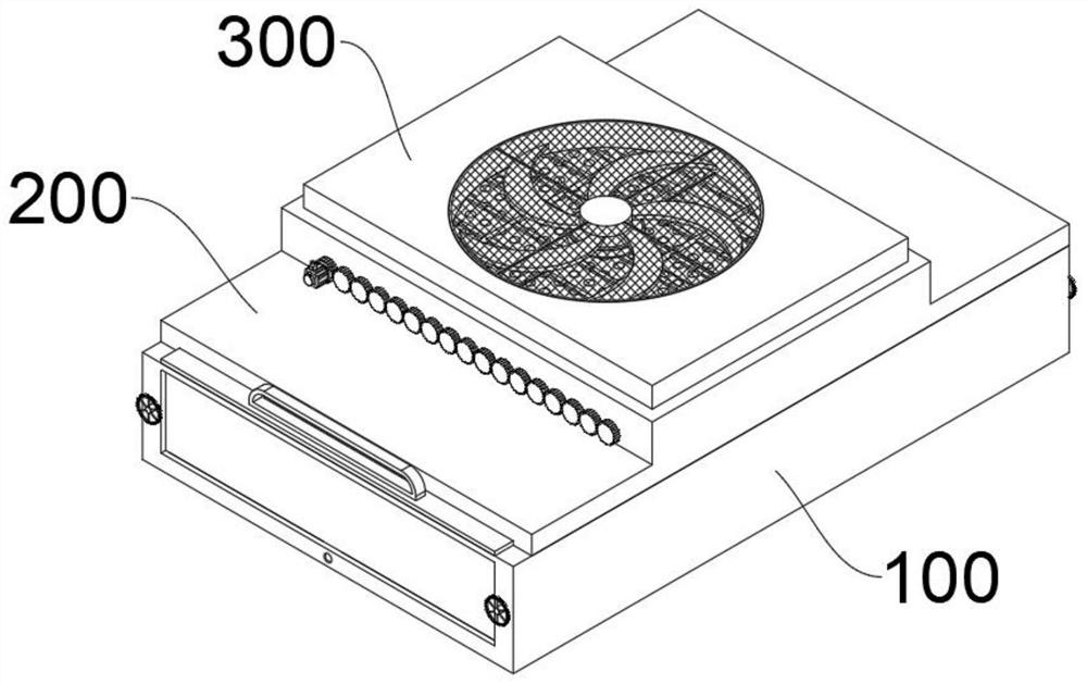
[0045] see Figure 1-Figure 13 As shown, the present embodiment provides a circuit board mounting case based on a desiccation protection mechanism, at least including:

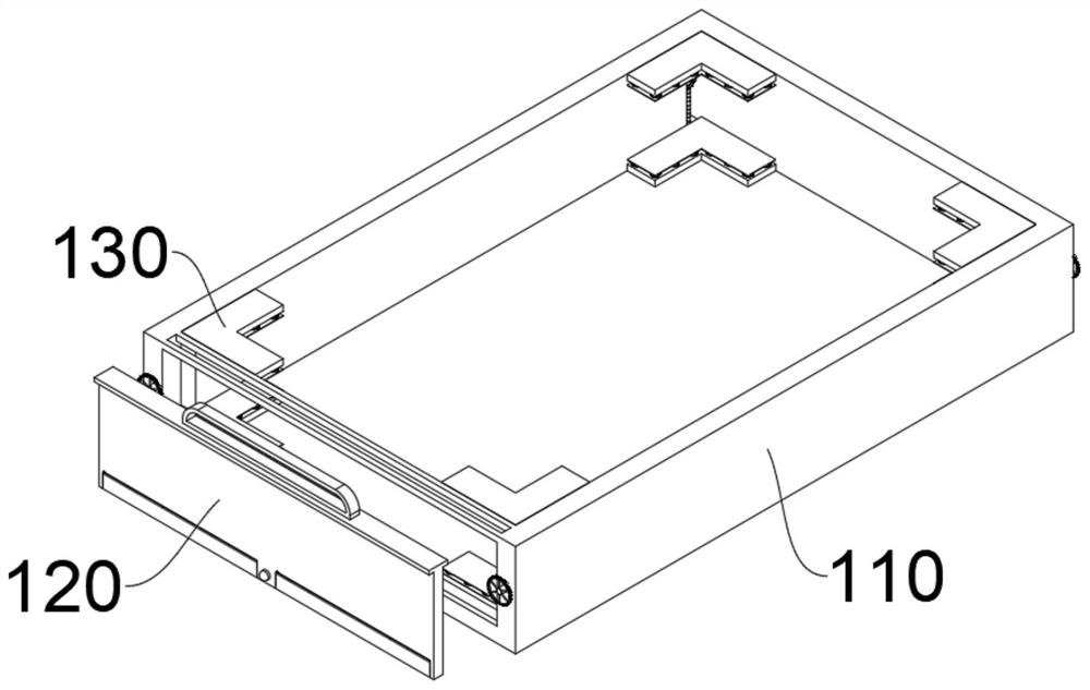
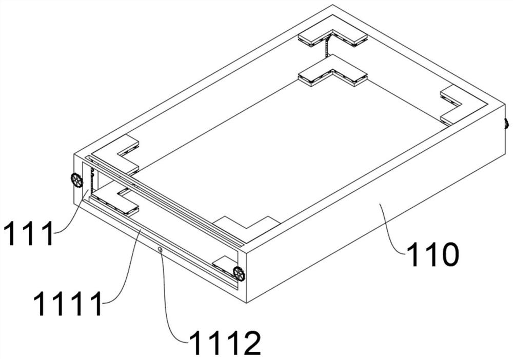
[0046] Install the protective mechanism 100, the installation protective mechanism 100 includes a protective shell 110, the end of the protective shell 110 is provided with a mounting groove 111, through the mounting groove 111, the circuit board can be inserted into the protective shell 110 from the inside of the mounting groove 111, which is convenient for installation, and the mounting groove 111 The inside is provided with a slot 1111, and the inside of the slot 1111 is inserted with a plugboard 120. Through the plugboard 120, after the circuit board is put into the inside of the protective case 110, the plugboard 120 can be inserted into the inside of the slot 1111, and the installation slot 111 Blocking not only prevents the circuit board from slipping out, but also prevents dust from entering the protec...


PUM

PropertyMeasurementUnit
Diameteraaaaaaaaaa

Abstract

The invention relates to the technical field of circuit board installation, in particular to a circuit board installation shell based on a drying protection mechanism. The shell at least comprises an installation protection mechanism, the installation protection mechanism comprises a protection shell, an installation groove is formed in the end of the protection shell, an insertion groove is formed in the installation groove, an insertion plate is inserted into the insertion groove, adjusting grooves are formed in the inner walls, close to the four corners, of the protection shell, and two symmetrical screw rods are rotationally arranged in the adjusting grooves; two symmetrical clamping plates are slidably arranged in the adjusting groove, adjusting plates are fixedly connected to the outer walls of the clamping plates, screw holes are formed in the surfaces of the adjusting plates, the drying shielding mechanism comprises a fixing plate, the fixing plate is fixed to the top of the protective shell, a cavity is formed in the top of the fixing plate, and a plurality of air holes are formed in the bottom of an inner cavity of the cavity at equal intervals; and according to the invention, the four corners of the circuit board can be fixed and protected, and the environment around the circuit board can be cooled and dried.

Description

technical field [0001] The invention relates to the technical field of circuit board installation, in particular to a circuit board installation shell based on a drying protection mechanism. Background technique [0002] The circuit board makes the circuit miniaturized and intuitive, and plays an important role in the mass production of fixed circuits and the optimization of the layout of electrical appliances. When the circuit board is installed, it is long and exposed in the equipment, and the outer wall of the circuit board is not protected, so that dust The surface of the circuit board that is easy to adhere causes corrosion damage, and the current circuit board does not have a drying function, and the water molecules in the air are easy to adhere to the surface of the circuit board, resulting in short-circuit damage to the circuit board and reducing the service life. In view of this, we propose Board mount housing based on dry protection mechanism. Contents of the inv...

Claims


Application Information

Patent Timeline
IPC IPC(8): H05K5/02H05K7/20B08B1/00
CPCH05K5/0217H05K7/20136B08B1/12Y02E60/10
Inventor 董银高
Owner 温州尚瑞光电科技有限公司
Why Eureka
Try Eureka