Brush head bristle flattening device

A flat wool and brush head technology, applied in the field of flat wool machines, can solve the problems of poor product consistency and low work efficiency

Active Publication Date: 2021-06-08
福建益顺塑胶有限公司
View PDF8 Cites 0 Cited by
  • Summary
  • Abstract
  • Description
  • Claims
  • Application Information

AI Technical Summary

Problems solved by technology

[0004] Therefore, in view of the above-mentioned problems, the present invention proposes a brush head flat hair device

Method used


Image

  • Brush head bristle flattening device
  • Brush head bristle flattening device
  • Brush head bristle flattening device

Examples


Embodiment Construction

[0031] The present invention will be further described in conjunction with the accompanying drawings and specific embodiments.

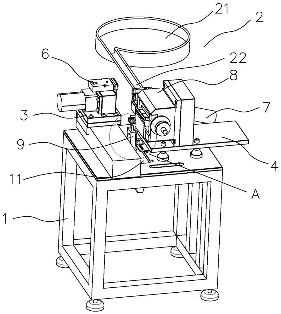
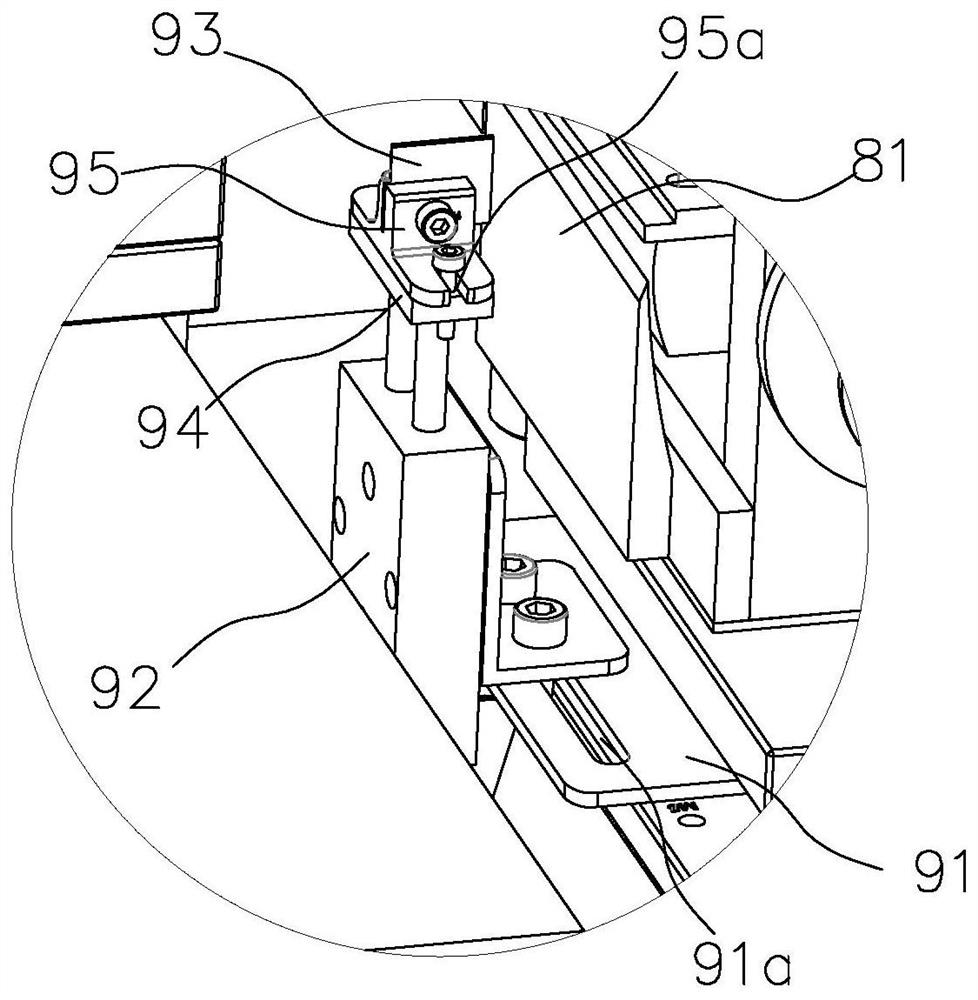
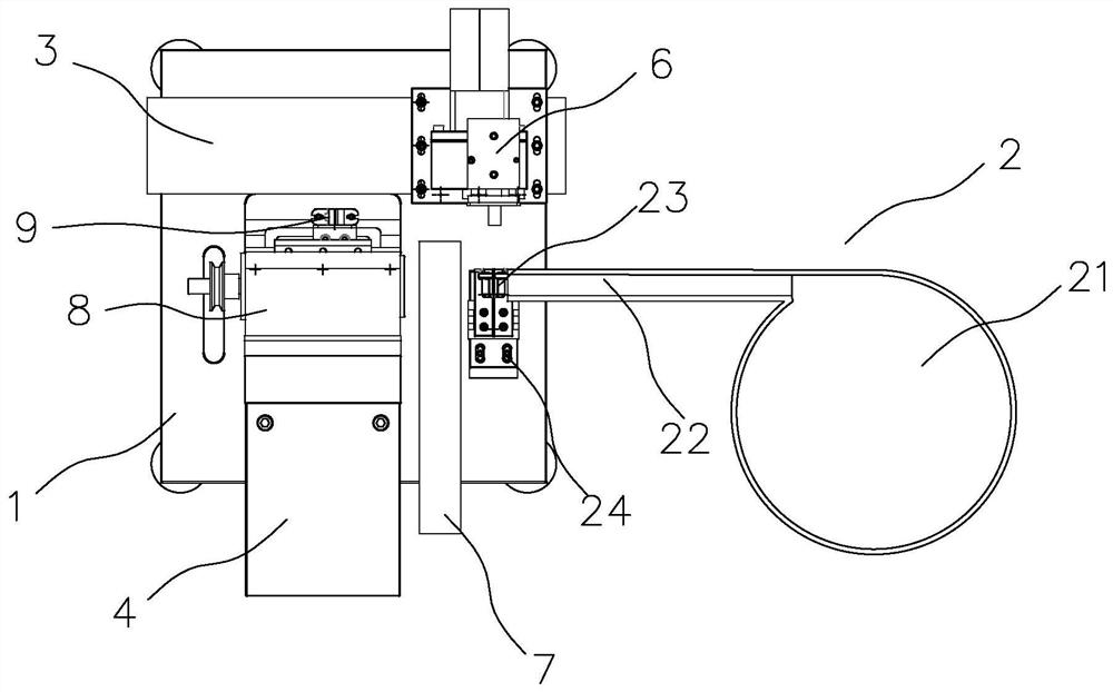
[0032] refer to Figure 1 to Figure 6 , the present embodiment provides a brush head flat bristle device, comprising a frame 1, an input device 2 arranged on the frame 1, a brush head pushing device 3 is provided on the side of the frame 1 opposite to the input device 2, the The frame 1 is provided with a support 4 on one side of the input device 2, the support 4 is provided with a brush head cutting device 5, and the brush head pushing device 3 includes a first device that can push the brush head to the brush head cutting device 5. A linear motion mechanism 31, a rotary mechanism 32 mounted on the first linear motion mechanism 31, and a fixed shaft 33 that can fix the brush head on the rotary mechanism 32, the brush head cutting device 5 includes a rotatable frame mounted on the bracket 4, the rotating shaft 51 on the rotating shaft 51, the tool ho...


PUM


Abstract

The invention belongs to the technical field of hair flattening machines and relates to a brush head hair flattening device. The device comprises a rack and an input device arranged on the rack; a brush head pushing device is arranged on the side, opposite to the input device, of the rack; a support is arranged on the side, located on the input device, of the rack; a brush head cutting device is arranged on the support; the brush head pushing device comprises a first linear motion mechanism capable of pushing a brush head to the brush head cutting device, a rotating mechanism arranged on the first linear motion mechanism and a fixing shaft arranged on the rotating mechanism and capable of fixing the brush head. The brush head cutting device comprises a rotating shaft rotationally arranged on the support, a knife rest fixed to the rotating shaft and a first knife head detachably connected to the knife rest; and the brush head pushing device is provided with a brush head discharging mechanism used for pushing the brush head to a next station. The technical problems that an existing hair flattening device is low in working efficiency and poor in product consistency are solved.

Description

technical field [0001] The invention relates to the technical field of flat wool machines, in particular to a brush head flat wool device. Background technique [0002] At present, the brush heads on the market will be uneven after high-speed hair planting. Chinese patent application number: CN201420792921.1 discloses a flat hair device, including a frame, a motor, a No. 1 fixing frame, a blade and a clamping part The motor is fixedly arranged on the frame, the No. 1 fixed frame is fixedly arranged on the frame at the front end of the motor, the clamping part is arranged on the front end of the No. 1 fixed frame, the blade is arranged on the No. 1 fixed frame through the rotating shaft, and the rotating shaft and the motor Connection; there is also a flat wool block on the No. 1 fixed frame facing the clamping part. The clamping part is composed of the No. 2 fixed frame, fixed block, top block, spring, ejector rod and handle. The fixed block passes through The rotating shaf...

Claims


Application Information

Patent Timeline
IPC IPC(8): A46D9/02B26D7/18
CPCA46D9/02B26D7/1863
Inventor 李剑风
Owner 福建益顺塑胶有限公司
Why Eureka
Try Eureka