Bronchoscope operation vehicle for anesthesiology department
A bronchoscope and operating vehicle technology, applied in the medical field, can solve the problems of affecting observation, unable to meet the needs of use, single function, etc., and achieve the effects of easy storage, reducing the space occupied, and improving stability.
- Summary
- Abstract
- Description
- Claims
- Application Information
AI Technical Summary
Problems solved by technology
Method used
Image

Examples
Embodiment 1
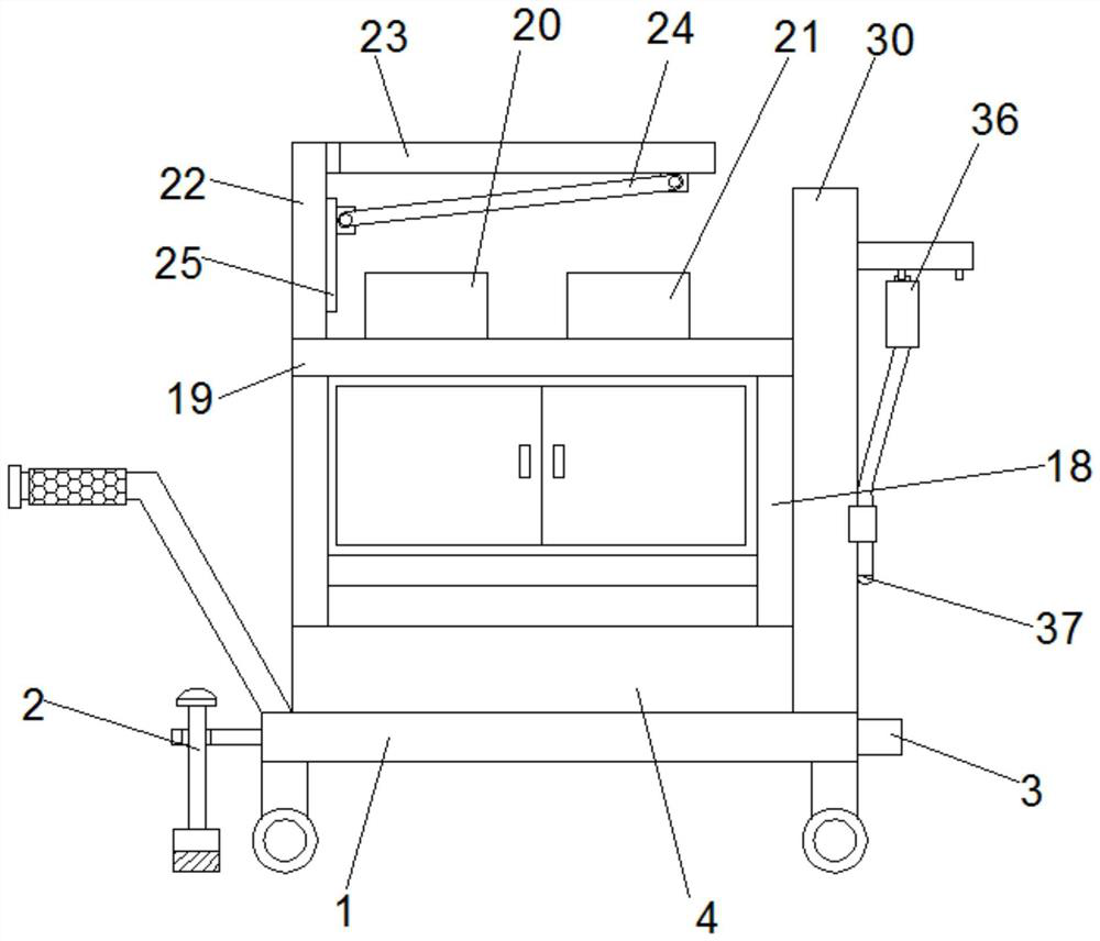
[0026] see Figure 1-8According to an embodiment of the present invention, a bronchoscopic operation cart for anesthesiology department includes a support base 1, a fixing mechanism 2 is installed on one side of the support base 1, and a fixing mechanism 2 is installed on the side of the support base 1 away from the fixing mechanism 2. There is an anti-collision mechanism 3, the top of the support seat 1 is provided with a shock absorber 4, the inside of the shock absorber 4 is provided with a shock absorber chamber, the inside of the shock absorber chamber is provided with a shock absorber base 5, and the shock absorber base 5 The bottom is symmetrically provided with a buffer column one, and a baffle plate 6 is installed on the shock-absorbing base 5 and between the buffer column one, and the bottom wall of the shock-absorbing cavity is symmetrically provided with a buffer column two, and the buffer column One end and one end of the buffer column two both pass through the li...
Embodiment 2
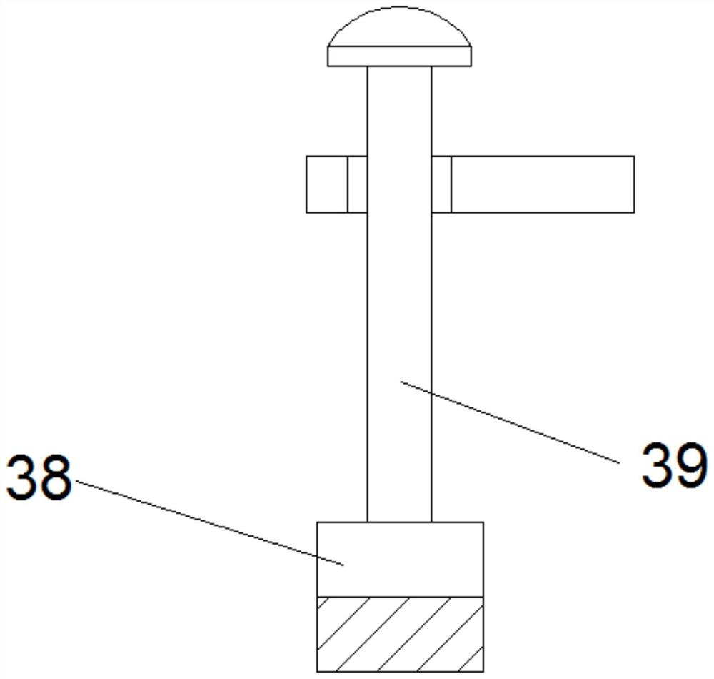
[0029] see Figure 1-8 , for the support base 1, the bottom of the support base 1 is symmetrically movable and provided with moving wheels. For the fixing mechanism 2, the fixing mechanism 2 includes a mounting plate, the mounting plate is fixed on one side of the support seat 1, and a threaded hole is opened on the mounting plate, and the internal thread connection of the threaded hole is provided with a screw thread. Rod 39, the bottom of the threaded rod 39 is provided with a pressing plate 38. The bottom of the pressing plate 38 is provided with a rubber pad, and the top of the threaded rod 39 is provided with a handle. For the support seat 1, a push armrest is fixed at one end of the top of the support seat 1, and an anti-slip and wear-resistant sleeve is provided on the outside of the push armrest. For the support frame 18, a storage cabinet is installed between the support frames 18, a sliding door is installed on the storage cabinet, and a handle is fixedly installed...
Embodiment 3
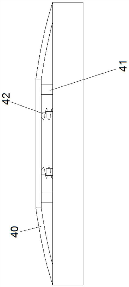
[0032] see Figure 1-8 , for the anti-collision mechanism 3, the anti-collision mechanism 3 includes an anti-collision beam 40 and an anti-collision layer, and an energy-absorbing box 41 and a telescopic rod are installed between the anti-collision beam 40 and the anti-collision layer, A damping spring 3 42 is sheathed on the outside of the telescopic rod. For the anti-collision layer, the anti-collision layer includes an anti-collision plate 43 and a buffer plate 44, a buffer cavity is provided between the anti-collision plate 43 and the buffer plate 44, and the elastic elastic material inside the buffer cavity is 45.
[0033] Through the above-mentioned scheme of the present invention, the beneficial effect: by being provided with the anti-collision beam 40, the anti-collision layer, the energy-absorbing box and the telescopic rod, when impacting, the energy-absorbing box 41 can absorb a part of the energy, and the anti-collision beam 40, the anti-collision layer , telesco...
PUM
 Abstract
Description
Claims
Application Information
 - R&D
- Intellectual Property
- Life Sciences
- Materials
- Tech Scout
- Unparalleled Data Quality
- Higher Quality Content
- 60% Fewer Hallucinations
Browse by: Latest US Patents, China's latest patents, Technical Efficacy Thesaurus, Application Domain, Technology Topic, Popular Technical Reports.
© 2025 PatSnap. All rights reserved.Legal|Privacy policy|Modern Slavery Act Transparency Statement|Sitemap|About US| Contact US: help@patsnap.com