Motor paint spraying production line and using method thereof

A production line and jet head technology, which is used in painting booths, manufacturing motor generators, and electric components, etc., can solve the problems of human injury and high labor intensity, and achieve the effect of reducing injury, reducing labor intensity and improving physical safety.

Pending Publication Date: 2021-06-08
仙居择栖农业机械有限公司
View PDF5 Cites 0 Cited by
  • Summary
  • Abstract
  • Description
  • Claims
  • Application Information

AI Technical Summary

Problems solved by technology

[0004] The purpose of the present invention is to solve the problem in the prior art that the labor intensity of manual spray painting is high and the spray paint causes harm to the human body, and a motor spray painting production line is proposed.

Method used


Image

  • Motor paint spraying production line and using method thereof
  • Motor paint spraying production line and using method thereof
  • Motor paint spraying production line and using method thereof

Examples


Embodiment 1

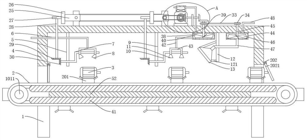
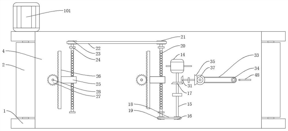
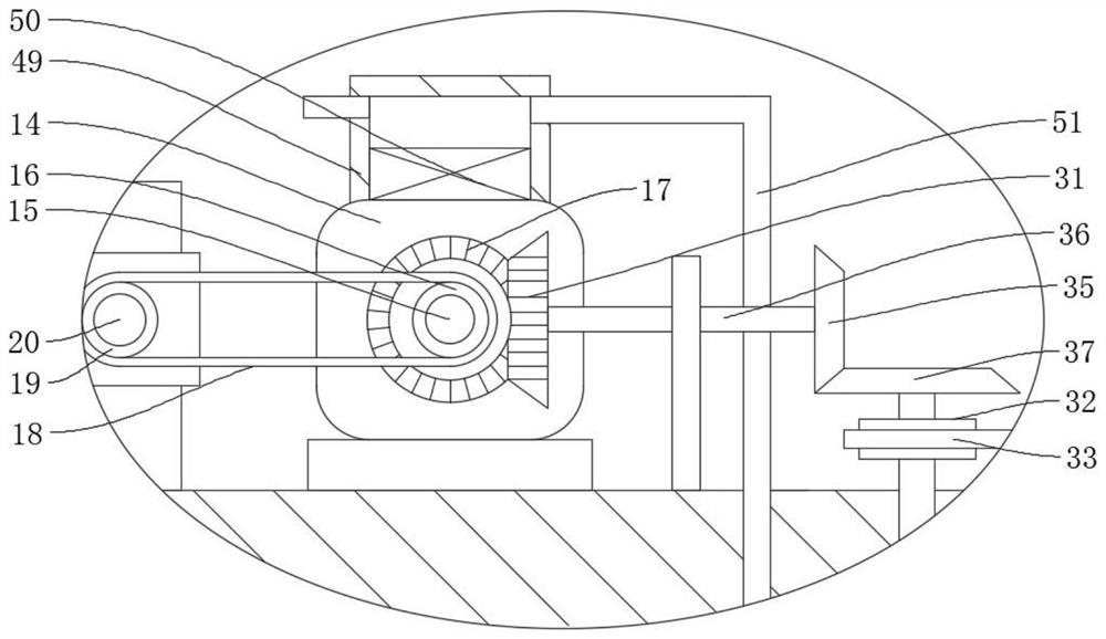
[0032] refer to figure 1 , figure 2 , image 3 , Figure 4 , a motor painting production line, including a workbench 1, a conveyor belt 2, a paint spraying mechanism, a drying mechanism, an exhaust mechanism and a painted part 3, the conveyor belt 2 is rotatably connected to the workbench 1, and the painted parts 3 are placed on the conveyor belt 2 , the workbench 1 is fixedly connected with a protective cover 4, the painting mechanism, the drying mechanism and the exhaust mechanism are all fixedly connected on the protective cover 4, and the protective cover 4 is fixedly connected with a driving mechanism, and the driving mechanism is connected with the painting mechanism and the drying mechanism. It is rotatably connected with the exhaust mechanism.

[0033] The painting mechanism includes a first fixed plate 5, a paint spray pipe 6, a first Z-shaped plate 7, and a paint spraying head 8. The first fixed plate 5 is fixedly connected to the protective cover 4, and the firs...

Embodiment 2

[0043] refer to figure 1 , a motor painting production line, including a workbench 1, a conveyor belt 2, a paint spraying mechanism, a drying mechanism, an exhaust mechanism and a painted part 3, the conveyor belt 2 is rotatably connected to the workbench 1, and the painted parts 3 are placed on the conveyor belt 2 , the workbench 1 is fixedly connected with a protective cover 4, the painting mechanism, the drying mechanism and the exhaust mechanism are all fixedly connected on the protective cover 4, and the protective cover 4 is fixedly connected with a driving mechanism, and the driving mechanism is connected with the painting mechanism and the drying mechanism. It is rotatably connected with the exhaust mechanism.

[0044] The painting mechanism includes a first fixed plate 5, a paint spray pipe 6, a first Z-shaped plate 7, and a paint spraying head 8. The first fixed plate 5 is fixedly connected to the protective cover 4, and the first Z-shaped plate 7 is rotatably connec...

Embodiment 3

[0054] An operation method of a motor painting production line, which adopts the following steps:

[0055] S1, start the second motor 101, the second motor 101 drives the conveyor belt 2 to rotate through the third rotating shaft 1011, and puts the painted part 3 on the placement seat 201 on the conveyor belt 2 into the protective cover 4 for painting;

[0056] S2, move the painted part 3 to the bottom of the painting head 8, stop the rotation of the second motor 101, then start the first motor 14, the first motor 14 drives the first Z-shaped plate 7 to rotate through the first transmission mechanism, and passes through the paint spraying pipe 6 Transport the spray paint into the paint spray head 8 to spray paint on the painted parts 3, and the first Z-shaped plate rotates back and forth at 180 degrees to spray paint in all directions on the painted parts 3, so as to improve the uniformity of painting;

[0057] S3, start the second motor 101 after the painting is completed to ...


PUM


Abstract

The invention discloses a motor paint spraying production line and a using method thereof, and belongs to the field of motor paint spraying. The motor paint spraying production line comprises a workbench, a conveying belt, a paint spraying mechanism, a drying mechanism, an exhaust mechanism and a paint-sprayed part, the conveying belt is rotationally connected to the workbench, the paint-sprayed part is placed on the conveying belt, and a protective cover is fixedly connected to the workbench; and the paint spraying mechanism, the drying mechanism and the exhaust mechanism are all fixedly connected to the protective cover, and the protective cover is fixedly connected with a driving mechanism. The motor paint spraying production line is easy to use and convenient to operate, paint spraying is conducted on a motor through automatic reciprocating rotation, the paint spraying comprehensiveness and uniformity are improved, the working efficiency is improved, the labor intensity of workers is reduced, meanwhile, the motor is dried through 180-degree reciprocating rotation, the drying efficiency and drying thoroughness are improved, and incomplete drying is reduced; and meanwhile, harmful gas generated during paint spraying is collected and discharged, harm of the harmful gas to the bodies of the workers is reduced, and the working safety is improved.

Description

technical field [0001] The invention relates to the technical field of motor painting, in particular to a motor painting production line and a method for using the same. Background technique [0002] The motor refers to an electromagnetic device that realizes the conversion or transmission of electric energy according to the law of electromagnetic induction; the motor is represented by the letter M in the circuit, and its main function is to generate driving torque, as a power source for electrical appliances or various machinery, to generate electricity The machine is represented by the letter G in the circuit, and its main function is to convert mechanical energy into electrical energy. [0003] As we all know, after the motor is assembled, the surface of the motor needs to be painted to improve the quality and aesthetics of the motor surface. At present, the surface painting process of the motor includes manual work and production line painting. The traditional manual wor...

Claims


Application Information

Patent Timeline
Patent Type & Authority Applications(China)
IPC IPC(8): B05B16/20B05B12/32B05B13/02B05D3/04H02K15/00
CPCB05B16/20B05B12/32B05B13/0278B05D3/04H02K15/00
Inventor 全叶琼
Owner 仙居择栖农业机械有限公司
Why Eureka
Try Eureka