Cleaning and reduction equipment system and method for waste oil-based mud during petroleum drilling

An oil-based mud, oil drilling technology, applied in chemical instruments and methods, earthwork drilling, sludge treatment, etc., can solve the problems of complicated operation, unfavorable placement of large-sized equipment, and excessively long conveyors.

Pending Publication Date: 2021-06-08
TIANJIN FANYINDETAI PETROLEUM ENVIRONMENTAL PROTECTION TECH DEV INC
View PDF0 Cites 0 Cited by
  • Summary
  • Abstract
  • Description
  • Claims
  • Application Information

AI Technical Summary

Problems solved by technology

The drilling area is small, which is not conducive to the placement of large-scale equipment. The oil-based mud is transported through the propeller at an angle of less than 30 degrees, and the conveyor is too long, which occupies a large area; and the forklift end requires a bucket lifting process, which is complicated to operate

Method used


Image

  • Cleaning and reduction equipment system and method for waste oil-based mud during petroleum drilling
  • Cleaning and reduction equipment system and method for waste oil-based mud during petroleum drilling
  • Cleaning and reduction equipment system and method for waste oil-based mud during petroleum drilling

Examples


Embodiment 1

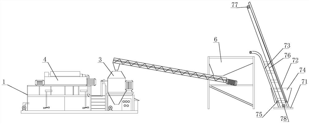
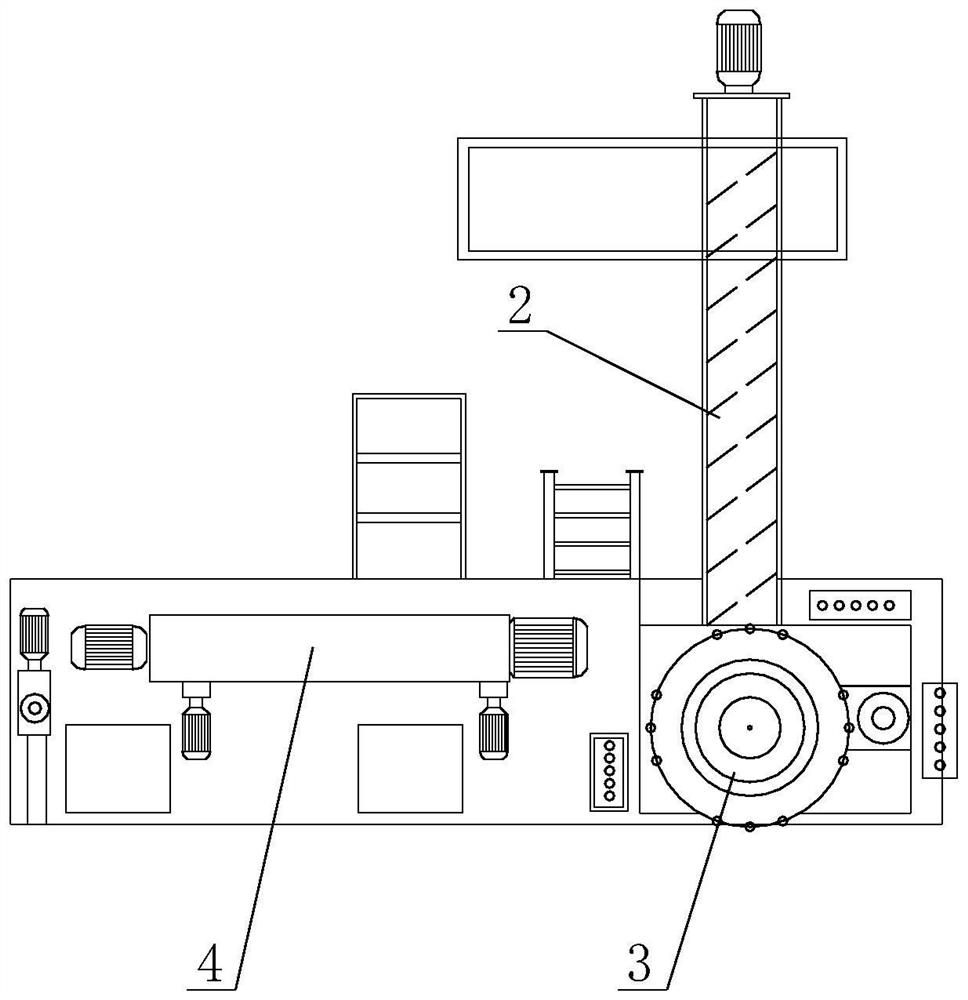
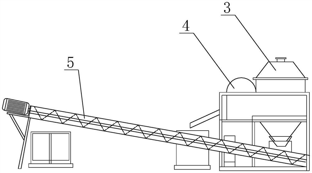
[0033] as attached Figure 1-3 As shown, an oil drilling while drilling waste oil-based mud cleaning and reduction equipment system includes a bracket 1, on which a first forward and reverse screw conveyor 2 is arranged, and one end of the first forward and reverse screw conveyor 2 is Feed, the other end is connected to the dryer 3, the dryer 3 is connected to the horizontal centrifuge 4 through the pipeline on the outer wall of the casing, and the outlet below the dryer 3 is provided with a second positive and negative screw conveyor machine 5, the mud outlet of the horizontal centrifuge 4 is connected to the second positive and negative screw conveyor 5, and the horizontal centrifuge 4 is connected to the drilling well through pipelines for transporting the treated waste oil base Mud for well drilling.

[0034] A first storage tank is arranged on the pipeline between the drying machine 3 and the horizontal centrifuge 4, and a submerged slurry pump is arranged in the first s...

Embodiment 2

[0041] This embodiment provides a method for cleaning and reducing waste oil-based mud during oil drilling. The waste drilling mud generated during oil drilling is received by the first positive and negative screw conveyor 1, and the mud can be transported to the drying machine by the shaftless screw conveyor. Dryer 3; the drying machine 3 screens out the large debris particles and transports them to the solid phase material area by the second positive and negative screw conveyor 5, and the separated mud enters the first mud storage tank and is pumped by the submerged slurry pump. into the horizontal centrifuge 4 for mud-water separation, and the horizontal centrifuge 4 separates the large coarse-grained sand and then transports it to the solid phase material area by the second positive and negative screw conveyor 5; the separated mud is returned to the solid phase material area through the mud pump. used in drilling.

[0042] When the amount of mud is large, part of the mud e...


PUM


Abstract

The invention relates to the technical field of petroleum drilling waste oil-based mud treatment, in particular to cleaning and reduction equipment system and method for waste oil-based mud during petroleum drilling. The equipment structurally comprises a support, a first positive and negative screw conveyor is arranged on the support, one end of the first positive and negative screw conveyor is used for feeding, the other end is connected with a spin dryer, the spin dryer is connected with a horizontal centrifugal machine through a pipeline on the outer wall of a machine shell of the spin dryer, a second positive and negative screw conveyor is arranged at an outlet in the lower portion of the spin dryer, a mud outlet of the horizontal centrifugal machine is communicated with the second positive and negative screw conveyor, and the horizontal centrifugal machine is communicated with a drilling well through a pipeline and used for conveying the treated waste oil-based mud for drilling. According to the cleaning and reduction equipment system for waste oil-based mud during petroleum drilling, mud non-landing equipment is adopted, waste mud is reduced and recycled, and in addition, mud-water separation and recycling of waste mud and rock debris can be achieved.

Description

technical field [0001] The invention relates to the technical field of physical treatment of oil-drilling waste oil-based mud, in particular to a cleaning and reduction equipment system and method for oil-drilling waste oil-based mud while drilling. Background technique [0002] Oil-based mud, also known as oil-based drilling fluid, is basically composed of oil, water, organic clay and oil-soluble chemical treatment agent. Oil-based mud is resistant to high temperature and salt and calcium erosion, which is beneficial to wellbore stability, good lubricity, and less damage to oil and gas layers. It is widely used in various drilling platforms. [0003] Waste oil-based mud from oil drilling is produced every moment during the drilling process of major oilfields in my country. Studies have shown that the chemical composition of oil-based mud commonly used in oilfields in my country makes the mud highly alkaline, highly corrosive, and difficult to transport. , and oil drilling w...

Claims


Application Information

Patent Timeline
Patent Type & Authority Applications(China)
IPC IPC(8): C02F11/127E21B21/06C02F103/10
CPCC02F11/127C02F2103/10C02F2303/06C02F2303/24E21B21/065
Inventor 赵勇
Owner TIANJIN FANYINDETAI PETROLEUM ENVIRONMENTAL PROTECTION TECH DEV INC
Why Eureka
Try Eureka