
Oil supply system and oil supply control method

An oil supply system and oil supply technology, applied in the field of compressors, can solve the problems of reducing the operating rate of piston compressors, lubricating oil loss, reduction, etc.

Active Publication Date: 2021-06-08
SGIS SONGSHAN CO LTD
View PDF8 Cites 0 Cited by
  • Summary
  • Abstract
  • Description
  • Claims
  • Application Information

AI Technical Summary

Problems solved by technology

[0003] The crankshaft connecting rod and slider are installed in the crankcase, and the crankcase is filled with lubricating oil when the compressor is stopped. The lubricating oil will be lost or reduced during the operation of the piston compressor. When the lubricating oil level in the crankcase is too low, it must Supplementing oil at shutdown reduces the operating rate of the piston compressor

Method used


Image

  • Oil supply system and oil supply control method
  • Oil supply system and oil supply control method
  • Oil supply system and oil supply control method

Examples


Embodiment Construction

[0039] In order to make the technical problems solved by the present invention, the technical solutions adopted and the technical effects achieved clearer, the technical solutions of the embodiments of the present invention will be further described in detail below in conjunction with the accompanying drawings. Obviously, the described embodiments are only the technical solutions of the present invention. Some, but not all, embodiments. Based on the embodiments of the present invention, all other embodiments obtained by those skilled in the art without creative efforts fall within the protection scope of the present invention.

[0040]In the description of the present invention, unless otherwise clearly specified and limited, the terms "connected", "connected" and "fixed" should be understood in a broad sense, for example, it can be a fixed connection, a detachable connection, or an integrated ; It can be a mechanical connection or an electrical connection; it can be a direct ...


PUM


Abstract

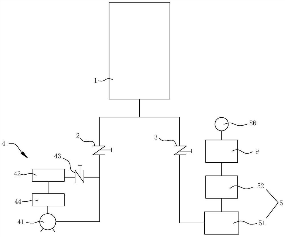
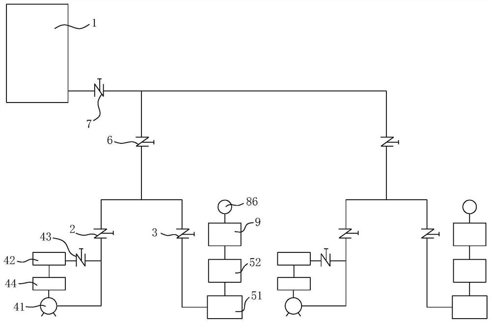
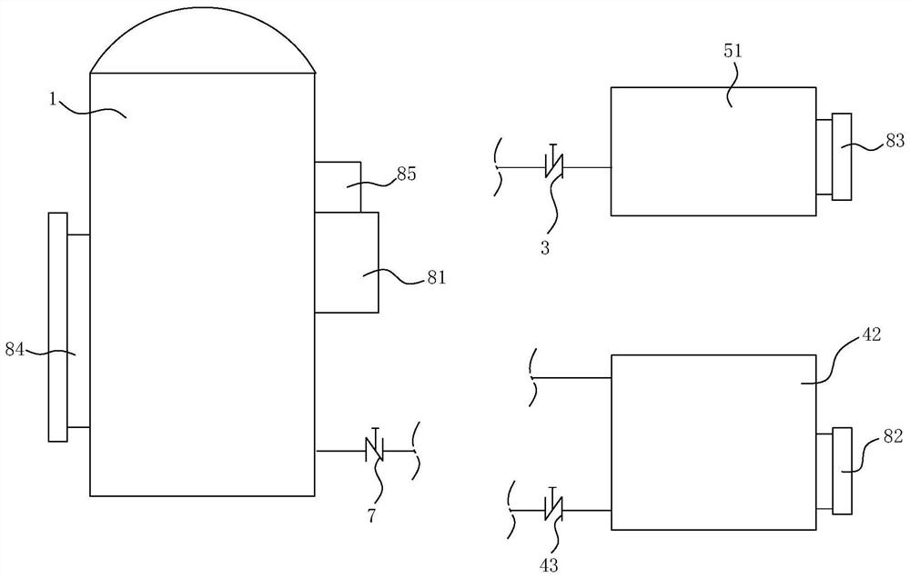
The invention relates to the technical field of compressors, and particularly discloses an oil supply system and an oil supply control method. The oil supply system comprises an oil supply tank, a first oil supply valve, a second oil supply valve, a crankcase oil supply mechanism and a piston oil supply mechanism, wherein the first oil supply valve is arranged between the oil supply tank and the crankcase oil supply mechanism, and the second oil supply valve is arranged between the oil supply tank and the piston oil supply mechanism, the crankcase oil supply mechanism comprises an oil pump, a crankcase body and a third oil supply valve, the oil pump, the crankcase body and the third oil supply valve annularly communicate, the first oil supply valve is arranged between the oil pump and the third oil supply valve, the piston oil supply mechanism comprises an oil injector and a piston body, the input end of the oil injector communicates with the second oil supply valve, and the output end of the oil injector communicates with the piston body. The oil supply system can continuously supply oil without shutdown or manual operation of an operator, and the working efficiency and the operating environment of a piston compressor can be guaranteed.

Description

technical field [0001] The invention relates to the technical field of compressors, in particular to an oil supply system and an oil supply control method. Background technique [0002] Gas piston compressors are widely used in metallurgical enterprises, and are mainly used to increase the gas pressure to meet the needs of gas users for gas pressure levels. In order to meet production needs, general metallurgical enterprises have a piston compressor station, and there are generally multiple piston compressors running in parallel in the station. The body of the piston compressor mainly includes the cylinder (mainly contains the piston body assembly), the middle body (mainly contains the crosshead parts), and the crankcase (mainly the connecting rod and crankshaft parts). When the piston body of the compressor moves, the gas is compressed into the gas pipeline, and the gas is transported through the gas pipeline. The lubrication system of the piston compressor is divided int...

Claims


Application Information

Patent Timeline
Patent Type & Authority Applications(China)
IPC IPC(8): F04B39/02
CPCF04B39/0207F04B39/0261F04B39/0284F04B39/0292
Inventor 危中良吴贝陈富林刘振辉戴金华陈再标蔡伟均李雪安江桂平劳海权
Owner SGIS SONGSHAN CO LTD
Learn More