Switch cabinet bus detection tool

A technology for detecting tooling and switchgear, which is applied in the direction of measuring devices, mechanical measuring devices, and mechanical devices, etc., can solve the problems that the busbar of switchgear is not easy to detect, etc., and achieve the goals of shortening the processing cycle, good versatility, and speeding up the delivery time Effect

Active Publication Date: 2021-06-08
TIANJIN PINGGAO INTELLIGENT ELECTRIC +2
View PDF6 Cites 2 Cited by
  • Summary
  • Abstract
  • Description
  • Claims
  • Application Information

AI Technical Summary

Problems solved by technology

[0004] The purpose of the present invention is to provide a switchgear busbar detection tool to solve the technical problem in the prior art that it is not easy to detect switchgear busbars of different sizes

Method used


Image

  • Switch cabinet bus detection tool
  • Switch cabinet bus detection tool
  • Switch cabinet bus detection tool

Examples


Embodiment 1

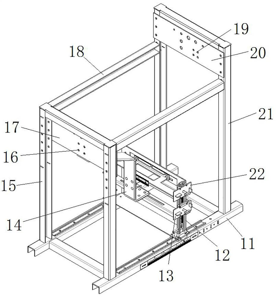
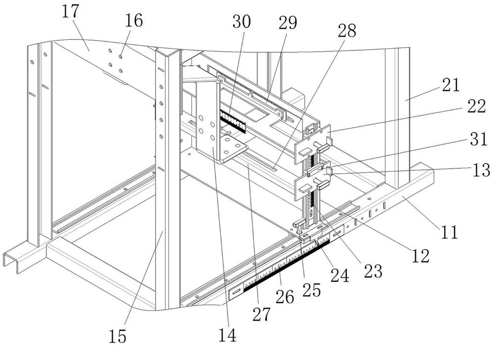
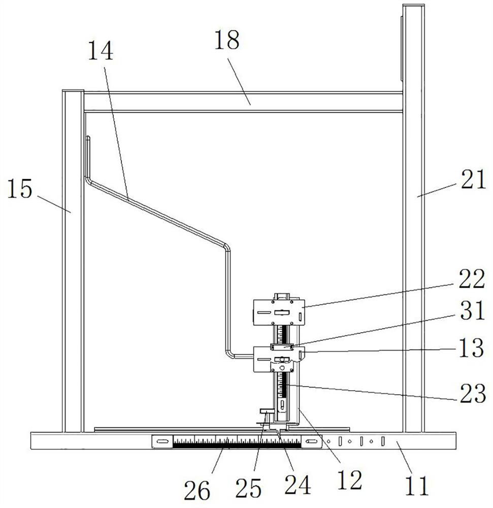
[0043] Such as figure 1 with figure 2 As shown, the switchgear bus detection tooling includes an underframe 11, the left and right ends of the underframe 11 are respectively provided with a first stand 15 and a second stand 21, between the first stand 15 and the second stand 21 The cross brace 18 is used to ensure the stability of the first stand 15 and the second stand 21 .

[0044]In this embodiment, the first stand 15 is fixed with a first fixing plate 17 by bolts, the first fixing plate 17 is provided with a first busbar fixing hole 16, and a plurality of first busbar fixing holes 16 are provided, and the first busbar The fixing hole 16 is used to fix one end of the busbar 14 of the switch cabinet; the number of the first busbar fixing holes 16 is multiple, and one or more than two first busbar fixing holes 16 form the first busbar fixing position, so that the first fixing plate 17 There are at least two first busbar fixing positions on the top, so that the tooling can ...

Embodiment 2

[0063] The difference between this embodiment and Embodiment 1 is that in Embodiment 1, the bus bar installation frame 13 is provided with a fixed long hole 28, and the fixed long hole 28 extends along the front and rear direction, and the fixed long hole 28 is used to fix the switch cabinet bus 14 the other end of the Wherein, the long fixing holes 28 form a plurality of second busbar fixing positions on the busbar installation frame 13 . In this embodiment, the busbar installation frame is provided with a plurality of fixed round holes, the fixed round holes are used to fix the other end of the switch cabinet busbar, and one or more than two fixed round holes form the second busbar fixing position, so that the busbar can be installed At least two second bus bar fixing positions are arranged on the frame.

Embodiment 3

[0065] The difference between this embodiment and Embodiment 1 is that in Embodiment 1, the left and right ends of the underframe 11 are respectively provided with a first stand 15 and a second stand 21, and the first stand 15 is fixed with bolts. The first fixed plate 17, the second stand 21 is fixed with the second fixed plate 20 by bolts, the position of the second fixed plate 20 is higher than the position of the first fixed plate 17, so that the frock can adapt to more different sizes Switchgear busbar 14. However, in this embodiment, when there are fewer types of switchgear busbars, only the first stand or the second stand is set on the bottom frame. At this time, the horizontal mounting plate and the first vertical mounting plate are arranged on the sliding frame on the same side.


PUM


Abstract

The invention relates to a switch cabinet bus detection tool. The switch cabinet bus detection tool comprises: a bottom frame; a vertical frame arranged on the bottom frame, wherein at least two first bus fixing positions are arranged on the vertical frame, and the first bus fixing positions are used for fixing one end of a switch cabinet bus; a sliding frame, wherein the sliding frame and the vertical frame are arranged in a spaced mode in the left-right direction, and the sliding frame is fixed to the bottom frame in a position adjustable mode in the left-right direction; and a bus mounting frame fixed on the sliding frame in a position adjustable mode in the vertical direction, wherein the bus mounting frame is provided with at least two second bus fixing positions, and the second bus fixing positions are used for fixing the other ends of the corresponding switch cabinet buses so as to be matched with the first bus fixing positions to detect the positions of the two ends of the switch cabinet buses. Through the tool, on-site verification of the switch cabinet bus in a bus processing area can be realized, the switch cabinet bus is prevented from being carried to a switch cabinet assembling area, the labor intensity is reduced, and the working efficiency is improved; and moreover, the switch cabinet bus can be processed in advance, so that the processing period is shortened, and the delivery time of products is shortened.

Description

technical field [0001] The invention relates to a detection tool for a bus bar of a switch cabinet. Background technique [0002] The switchgear busbar is the current transmission carrier of the switchgear. Due to the limited internal space of the switchgear cabinet, in order to ensure the insulation performance of the high-voltage circuit, the structure of the switchgear busbar that generally carries current is irregular, and in different switchgears, the switchgear busbar The structure is also different, which makes the standardization of the switchgear busbar low. [0003] Due to the complex and different structures of the switchgear busbars, the switchgear busbars cannot be detected with conventional detection tools. Generally, after the overall assembly of the switchgear is completed, the actual required connection dimensions are measured on-site before the busbar processing is performed. Moreover, in order to ensure the assembly accuracy, the assembly verification of ...

Claims


Application Information

Patent Timeline
Patent Type & Authority Applications(China)
IPC IPC(8): G01B5/02
CPCG01B5/02
Inventor 张罗锐汪宁陈利民杜敬敬丛艳伟康世荣王爽吴登刘非非王茜王春雷陶璟辰桑永健
Owner TIANJIN PINGGAO INTELLIGENT ELECTRIC
Why Eureka
Try Eureka