Method for measuring residual magnetism in shielding barrel based on in-situ magnetometer

A measurement method and magnetometer technology, applied in the field of atomic sensors, can solve problems such as complex operation and inability to reflect the shielding effect of shielding barrels on environmental residual magnetism, and achieve the effect of simple and convenient measurement operation, convenient design and testing

Active Publication Date: 2021-06-08
BEIHANG UNIV
View PDF7 Cites 4 Cited by
  • Summary
  • Abstract
  • Description
  • Claims
  • Application Information

AI Technical Summary

Problems solved by technology

[0004] The present invention solves the problem that the existing measuring method requires an additional sensor to cause complex operation and because the influence of the optical frequency shift is not considered, the measured magnetic field is the superposition of the actual remanence and the false magnetic field generated by the optical frequency shift, which cannot reflect the environmental remanence of the shielding barrel In order to solve the problems of shielding ef...

Method used


Image

  • Method for measuring residual magnetism in shielding barrel based on in-situ magnetometer
  • Method for measuring residual magnetism in shielding barrel based on in-situ magnetometer
  • Method for measuring residual magnetism in shielding barrel based on in-situ magnetometer

Examples


Embodiment Construction

[0016] The present invention will be further described below in conjunction with the accompanying drawings and specific embodiments.

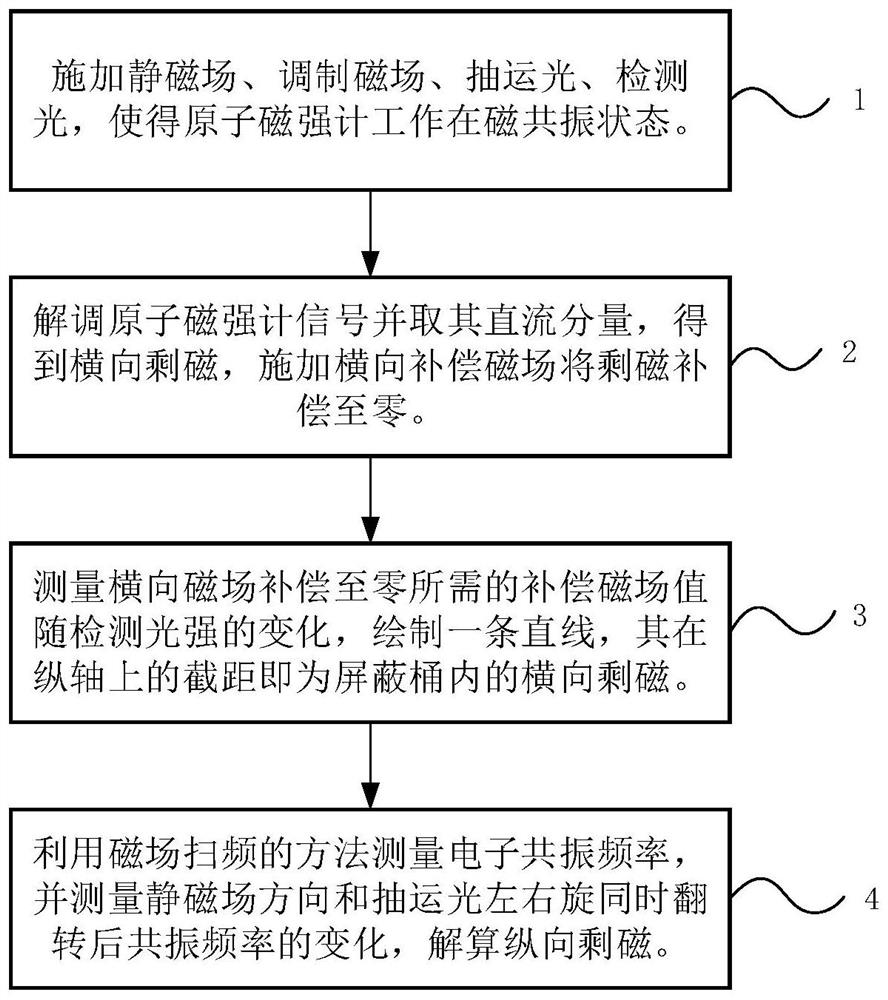
[0017] Concrete implementation steps of the present invention are as figure 1 As shown, a total of 4 steps are included, and the specific steps are as follows:

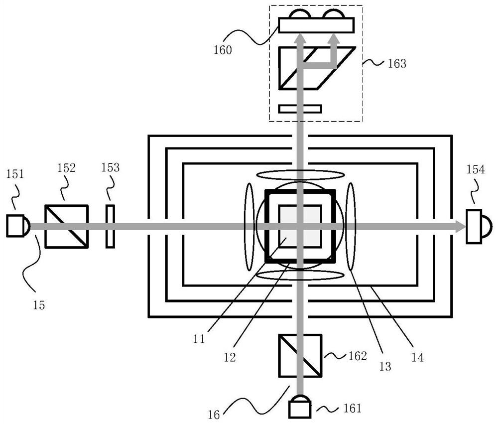
[0018] Step 1. Build an atomic sensor system, including an atomic gas chamber, an oven, a three-axis coil, a multi-layer magnetic shielding barrel, a pumping optical path, and a detection optical path. Then apply a static magnetic field in the longitudinal direction, that is, the direction of the pumping light, and apply circularly polarized pumping light to polarize the atoms, and the atoms will precess around the static magnetic field. Then apply a modulated magnetic field with the same frequency as the atomic precession in the longitudinal direction to make the atomic magnetometer work in a resonance state, and use a beam of linearly polarized detection light to detect the atomic p...


PUM


Abstract

The invention discloses a method for measuring residual magnetism in a shielding barrel based on an in-situ magnetometer, and is suitable for testing the residual magnetism in the shielding barrel of an atomic sensor. The method comprises the steps of firstly, applying a static magnetic field, a modulation magnetic field, pumping light and detection light to enable an atom magnetometer to work in a magnetic resonance state; demodulating a magnetometer signal, extracting a direct-current component of the magnetometer signal by using a low-pass filter to obtain the residual magnetism in the transverse direction, namely the direction perpendicular to a static magnetic field, and applying a direct-current compensation magnetic field in the transverse direction to compensate the residual magnetism to zero; and carrying out residual magnetism measurement and compensation under different detection light intensities, so that it is found that the output value of a compensation magnetic field linearly changes along with the detection light intensities, and the intercept of a straight line on a longitudinal axis is the value of the transverse actual residual magnetism after light frequency shift is eliminated. The electronic resonance frequency is measured by using a magnetic field frequency sweeping method, and the change of the resonance frequency after the static magnetic field direction and the left and right rotation of the pumping light are turned at the same time is measured, and the longitudinal actual residual magnetism can be obtained by dividing the change by two times of the alkali metal gyromagnetic ratio. According to the present invention, an external sensor is not needed, and the design of the atom sensor is greatly facilitated.

Description

technical field [0001] The invention relates to the field of atomic sensors, in particular to a method for measuring residual magnetism in a shielding bucket based on an in-situ magnetometer. Background technique [0002] In recent years, with the rapid development of atomic physics, breakthroughs in theories such as quantum optics and cold atoms, and advances in technologies such as lasers and quantum manipulation, atomic sensors have gradually attracted attention and attention. High-precision and high-sensitivity atomic sensors are widely used in time measurement, inertial measurement, magnetic field measurement and other fields, and some of them have achieved engineering applications, bringing about major technological changes. Because the atomic energy level is very sensitive to the magnetic field, magnetic shielding is generally required in the atomic sensor to reduce the interference of the ambient magnetic field on the atoms. Magnetic shielding usually requires carefu...

Claims


Application Information

Patent Timeline
IPC IPC(8): G01R33/12
CPCG01R33/1215
Inventor 刘占超贾雨棽刘刚田昊武泽坤茅耘恺
Owner BEIHANG UNIV
Why Eureka
Try Eureka