Pixel driving circuit, active electroluminescent display and driving method

A pixel drive circuit and luminescent technology, applied in static indicators, instruments, etc., can solve problems such as limited number of gray scales, wrong contours, and color shift of MicroLEDs

Active Publication Date: 2021-06-08
SOUTH CHINA UNIV OF TECH
View PDF8 Cites 12 Cited by
  • Summary
  • Abstract
  • Description
  • Claims
  • Application Information

AI Technical Summary

Problems solved by technology

[0004] Although some people in the prior art have proposed an active driving scheme for Micro LED based on PWM (Pulse Width Modulation), for the active digital PWM driving scheme, since the grayscale is represented by the molecular frame method, it can represent The number of grayscales is limited and produces false contours
For the active analog PWM driving scheme, since the slope setting of the slope control signal is relatively small, the rise time or fall time of the generated PWM signal is relatively long, which makes the Micro LED display at low gray levels produce color shift, Uneven brightness, etc.

Method used


Image

  • Pixel driving circuit, active electroluminescent display and driving method
  • Pixel driving circuit, active electroluminescent display and driving method
  • Pixel driving circuit, active electroluminescent display and driving method

Examples


Embodiment 1

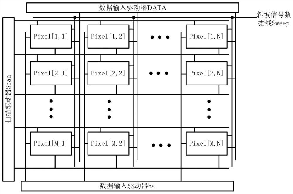
[0054] Such as image 3 As shown, the structure of an active electroluminescent display device basically consists of a pixel array component Pixel, a scan driver Scan, a data input driver DATA, and a data input driver ba. The pixel array components are connected to the scan lines SCAN arranged in rows, the first data signal lines and the second data signal lines arranged in columns, and the pixel array components also include a plurality of power lines for providing the required power supply lines for the operation of the pixels. Low potential power supply VSS and high potential power supply VDD. The first data signal line required for the operation of the pixel is used to control the pulse width of the PWM signal, the second data signal line is used to control the output current of the current source, the low potential power supply VSS is also used for grounding, and the high potential power supply VDD is used for supplying to the The pixel provides power supply, the first d...

Embodiment 2

[0083] Such as image 3 As shown, the structure of the active electroluminescent display in the second embodiment is basically composed of a pixel array component Pixel, a scan driver Scan, a data input driver DATA, and a data input driver ba. The pixel array part is connected to the scan line SCAN arranged in rows, the first data signal line and the second signal data line arranged in columns, and the pixel array part also includes a plurality of power lines for providing the pixel operation required Low potential power supply VSS and high potential power supply VDD. The first data signal line required for the operation of the pixel is used to control the pulse width of the PWM signal, the second data signal line is used to control the output current of the current source, the low potential power supply VSS is also used for grounding, and the high potential power supply VDD is used for supplying to the The pixels provide the power supply.

[0084] The display device of the ...

Embodiment 3

[0098] Such as Figure 8 As shown, the structure of an active electroluminescent display in Embodiment 3 basically consists of a pixel array component Pixel, a scanning driver Scan, a data input driver DATA, and a data input driver ba. The pixel array components are connected to the scan lines SCAN arranged in rows, the first data signal lines and the second data signal lines arranged in columns, and the pixel array components also include a plurality of power lines for providing the required power supply lines for the operation of the pixels. Low potential power supply VSS and high potential power supply VDD. The first data signal line required for the operation of the pixel is used to control the pulse width of the PWM signal, the second data signal line is used to control the output current of the current source, the low potential power supply VSS is also used for grounding, and the high potential power supply VDD is used for supplying to the The pixel provides power suppl...


PUM


Abstract

The invention discloses a pixel driving circuit, an active electroluminescent display and a driving method. The pixel driving circuit comprises a light-emitting element; a current source including a driving transistor connected to the light-emitting element and providing driving currents having different amplitudes to the light-emitting element according to a voltage applied to a gate terminal of the driving transistor; a current control circuit connected with the current source and used for providing voltages with different levels for the gate terminal of the driving transistor; a PWM generation circuit used for generating a PWM pulse signal for controlling the on time of the light-emitting element; a shaping circuit used for shaping the PWM pulse signal; and a PWM control circuit used for obtaining the duration for controlling the driving current of the light-emitting element according to the shaped PWM pulse signal and the output voltage of the current control circuit. According to the invention, a ramp signal is input after the scanning control signal of each row is input, so that a relatively large PWM pulse width can be realized.

Description

technical field [0001] The invention relates to the field of photoelectric display, in particular to a pixel driving circuit, an active electroluminescence display and a driving method. Background technique [0002] Compared with traditional liquid crystal display (LCD) and organic light-emitting diode display (OLED), micro-light-emitting diode (MicroLED) display technology is known for its display advantages of high brightness, high contrast, wide color gamut, long life, and nanosecond-level response speed. For the ultimate display technology. However, at present, Micro LED display technology has encountered some technical challenges, including chip manufacturing, mass transfer, monolithic integration technology, colorization implementation scheme, driving circuit design, etc. Compared with OLED, Micro LED has a very steep I-V characteristic, and the luminous efficiency will decrease at low current density, and it will cause the problem of color shift of Micro LED under di...

Claims


Application Information

Patent Timeline
Patent Type & Authority Applications(China)
IPC IPC(8): G09G3/32G09G3/3225
CPCG09G3/32G09G3/3225
Inventor 吴为敬邹培安刘淳徐延港梅相霖徐苗王磊彭俊彪
Owner SOUTH CHINA UNIV OF TECH
Why Eureka
Try Eureka