
Active antenna device

An antenna device and active antenna technology, which is applied to antenna supports/installation devices, antennas, and antenna components, etc., can solve the problems of poor broadband performance, increased antenna weight and cost, and weak antenna stability against wind, etc. The effect of optimal antenna performance, operating bandwidth optimization, and spectral response optimization

Active Publication Date: 2021-06-08
NAT ASTRONOMICAL OBSERVATORIES CHINESE ACAD OF SCI
View PDF6 Cites 0 Cited by
  • Summary
  • Abstract
  • Description
  • Claims
  • Application Information

AI Technical Summary

Problems solved by technology

One is a flexible structure antenna (LOFAR), which uses a thin wire as an array antenna. In order to maintain the stability of the antenna, the LOFAR antenna is connected to an elastic zipper through the wire itself, and then fixed to the ground through ground nails. In this way, the antenna is realized. The low-noise amplifier of the antenna is located at the top of the pole of the antenna, and is sealed in a circular resin module as a whole. Since the structure of this antenna is a basic element antenna, its broadband performance is relatively poor, and once the antenna is manufactured and After the installation is completed, the length is fixed, and the spectral response and working frequency band of the antenna system will also be difficult to adjust
The other is a rigid structure (LWA) antenna, which uses rigid materials to make the antenna. Although the broadband characteristics can be achieved by changing the shape of the antenna, since there is no additional support structure, in order to maintain the shape of the antenna, the structure of the antenna needs to be If it is strong enough, it will inevitably increase the weight and cost of the antenna, and the antenna's ability to resist wind and stability is weak

Method used


Image

  • Active antenna device
  • Active antenna device
  • Active antenna device

Examples


Embodiment Construction

[0034] In order to make the object, technical solution and advantages of the present invention clearer, the present invention will be further described in detail below in conjunction with specific embodiments and with reference to the accompanying drawings.

[0035] It should be understood, however, that these descriptions are exemplary only, and are not intended to limit the scope of the present disclosure. In the following detailed description, for purposes of explanation, numerous specific details are set forth in order to provide a thorough understanding of the embodiments of the present disclosure. It may be evident, however, that one or more embodiments may be practiced without these specific details. Also, in the following description, descriptions of well-known structures and techniques are omitted to avoid unnecessarily obscuring the concept of the present disclosure.

[0036] The terminology used herein is for the purpose of describing particular embodiments only, a...


PUM


Abstract

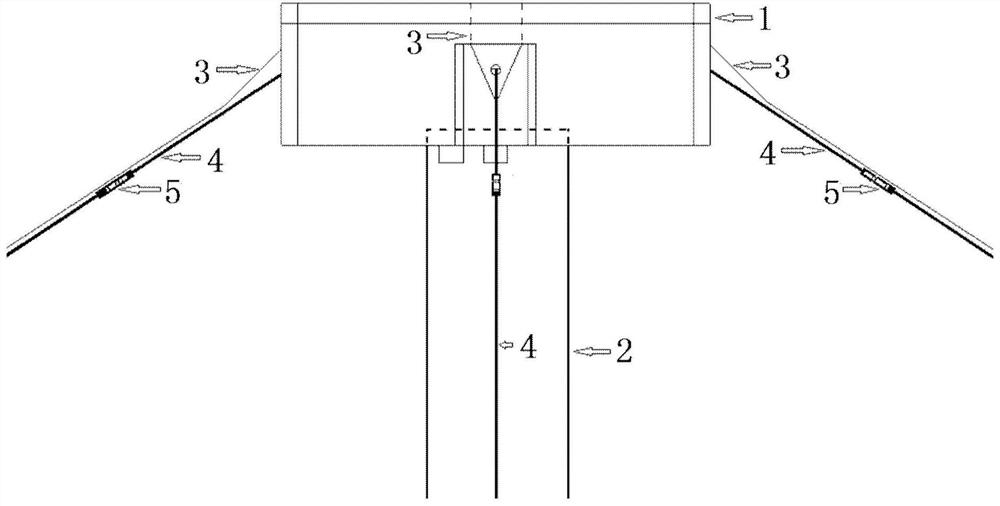
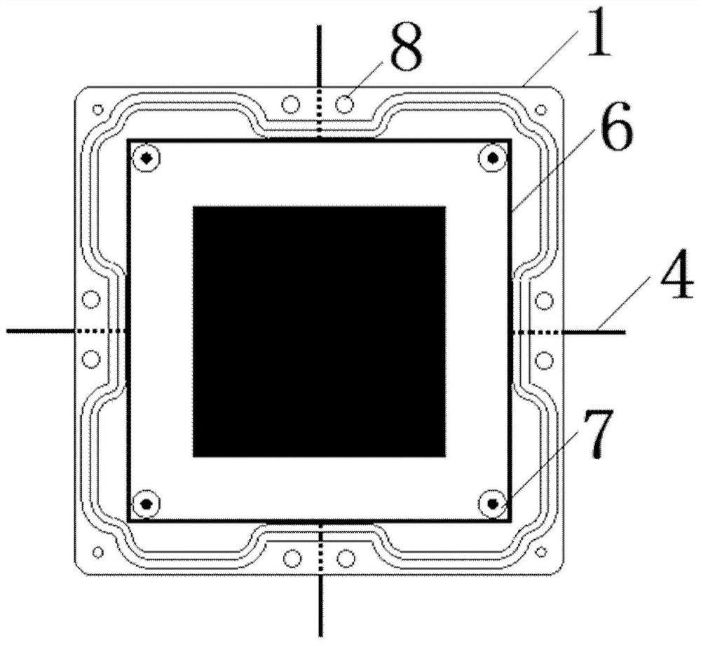
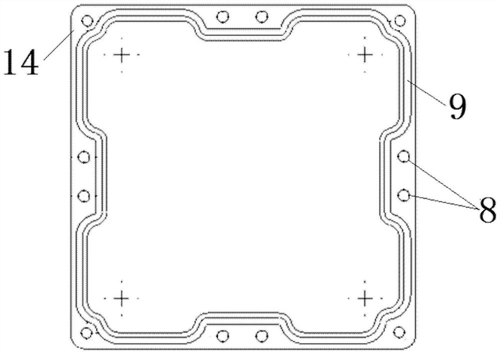
The invention discloses an active antenna device, and the device comprises a mounting box which is provided with a mounting cavity and a fixing hole, wherein the mounting cavity is used for fixing a low-noise amplifier in the mounting box; an antenna used for receiving signals, wherein the antenna comprises a connecting section and a lengthening section, and the connecting section is used for being connected with the low-noise amplifier; and a fixing rope which is used for fixing the mounting box and the antenna and is fixed on the fixing hole. According to the active antenna device provided by the invention, the antenna and the fixing rope are separately and independently arranged, the number, length and inclination angle of the fixing rope can be changed according to implementation requirements, and meanwhile, the antenna is fixed by the fixing rope, so that the shape of the antenna can be adaptively adjusted according to different forms of the fixing rope, therefore, antennas in different forms can be obtained, and different antenna performances can be obtained.

Description

technical field [0001] The invention belongs to the technical field of radio astronomy and communication, and in particular relates to an active antenna device. Background technique [0002] In radio astronomy, very low frequency (VLF, frequency<30MHz), also known as ultra-long wave (ULW, wavelength>10m), as one of the last unobserved frequency bands, is exploring unknown astronomical phenomena and the darkness of the universe. Significant discoveries are expected to be made in fields such as the age of space, the evolution of extragalactic radio sources, and the distribution of the interstellar medium. However, due to the cut-off of the earth's ionosphere and a large amount of man-made radio interference, ground-based very low frequency radio observations are greatly limited, so space-based very low frequency radio telescopes are needed. The very low frequency radio astronomy exploration being carried out on Chang'e-4 is the latest exploration in this field in recent...

Claims


Application Information

Patent Timeline
Patent Type & Authority Applications(China)
IPC IPC(8): H01Q1/12H01Q3/01H01Q1/00H01Q23/00
CPCH01Q1/12H01Q3/01H01Q1/002H01Q23/00
Inventor 陈林杰
Owner NAT ASTRONOMICAL OBSERVATORIES CHINESE ACAD OF SCI
Learn More