Shaft-end permanent magnet power generation device and bogie comprising same

A permanent magnet power generation and bogie technology, which is applied to electromechanical devices, circuit devices, battery circuit devices, etc., can solve the problems of separate shaft design, inability to install bogie power generation devices, and difficulty in matching dynamic parameters.

Pending Publication Date: 2021-06-08
CHANGSHA UNIVERSITY OF SCIENCE AND TECHNOLOGY
View PDF1 Cites 0 Cited by
  • Summary
  • Abstract
  • Description
  • Claims
  • Application Information

AI Technical Summary

Problems solved by technology

[0003] In the prior art, the installation of the power generation device on the bogie needs to be arranged separately on the bogie, and the belt drive is used, so the bogie shaft needs to be designed separately; since the motor cannot be center-symmetrical on the bogie, it is difficult to match its dynamic parameters
At the same time, due to the increase of the sprung mass of the motor, the dynamic performance of the bogie will become worse
Moreover, the bogie with the power generation device on the bogie is generally a passenger car bogie, and its frame is an integral structure that can be fixed and installed; The bogie power generation unit cannot be installed
[0004] The patent "Axle End Disc Permanent Magnet Generating Device for Railway Freight Cars (Patent No.: 201210561240.X)" installs the generating device on the axle of the train, which solves the problem that the generating device occupies a large space on the bogie, the shaft is designed separately, and the steering of the truck However, the device covers the stator structure and rotor structure inside the axle box end cover, and is fixedly connected with the axle box bearing seat sleeved on the axle through the axle box end cover. For the installation basis, this structure makes the axle box bearing seat, stator structure, rotor structure and axle diameter need to be used together

Method used


Image

  • Shaft-end permanent magnet power generation device and bogie comprising same
  • Shaft-end permanent magnet power generation device and bogie comprising same
  • Shaft-end permanent magnet power generation device and bogie comprising same

Examples


Embodiment 1

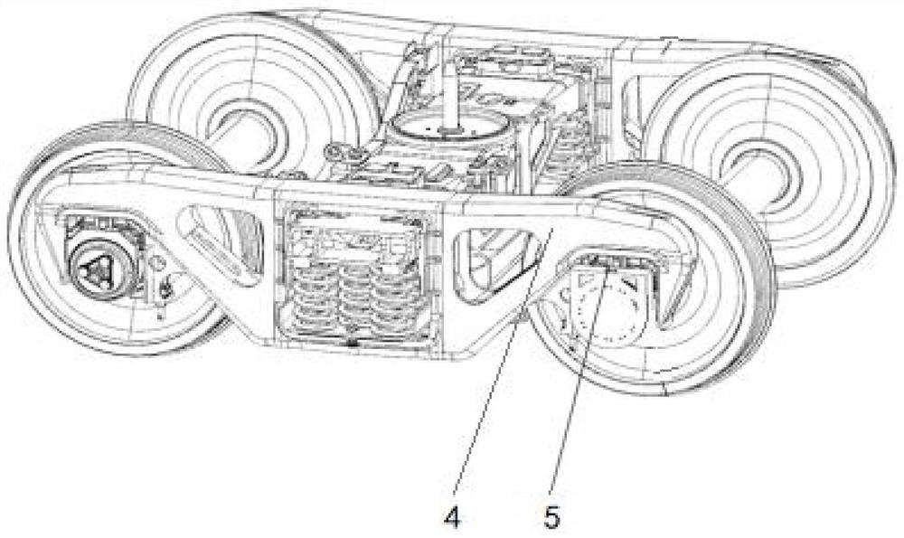
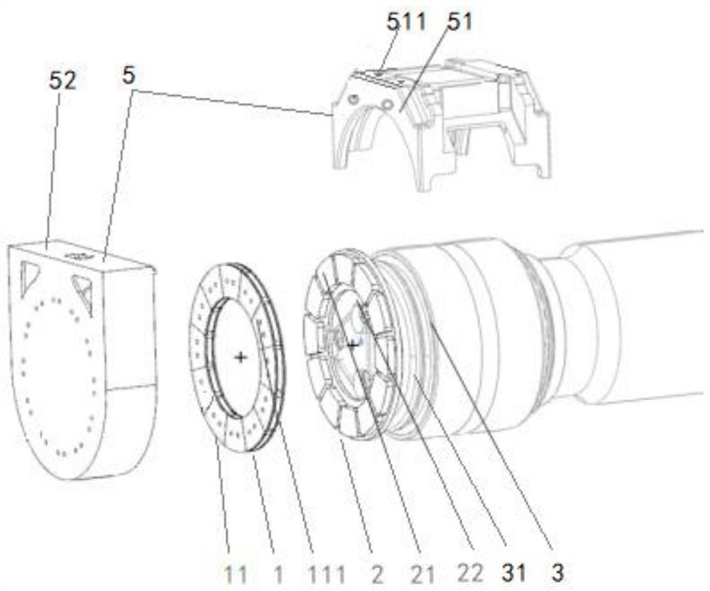
[0038] Such as Figure 1 to Figure 4 As shown, the shaft-end permanent magnet generator of this embodiment includes a stator assembly 1 and a rotor assembly 2. The rotor assembly 2 is installed on the shaft end of the rotating shaft 3 of the bogie and rotates with the rotating shaft 3. The stator assembly 1 is fixed on the bogie. On the frame body 4, a working space with adjustable radial and / or axial distances is formed between the stator assembly 1 and the rotor assembly 2, and the relative position of the stator assembly 1 and the rotor assembly 2 meets the corresponding requirements for generating electromagnetic induction current . When the car body is running normally, the rotating shaft 3 rotates with the rotor assembly 2, and the stator assembly 1 moves to cut the magnetic force line to generate a magnetically induced electromotive force, and then forms a control loop according to the electromagnetic coil terminal of the stator assembly 1, and generates a current. The...

Embodiment 2

[0050] Such as Figure 5 to Figure 8 As shown, the second embodiment of the shaft-end permanent magnet generator of the present invention, the generator is basically the same as the generator of Example 1, the only difference being:

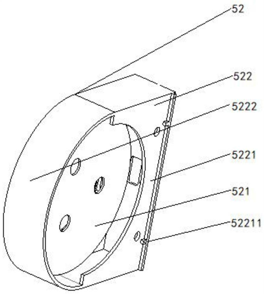
[0051] In this embodiment, the fixing plate 521 is provided with an assembly hole 5211 , the stator assembly 1 is fixed in the assembly hole 5211 and covered by the housing 522 , and the housing 522 is connected with the saddle 51 and forms a shield for the rotor assembly 2 . The housing 522 is detachably connected to the saddle 51 by bolts, the housing 522 is connected to the fixing plate 521 by bolts, the assembly hole 5211 is a through hole, and the stator assembly 1 is embedded in the assembly hole 5211 .

[0052] In this embodiment, the stator assembly 1 includes an electromagnetic coil 12, a coil front gland 13 and a coil rear gland 14. The electromagnetic coil 12 is set in the assembly hole 5211, and the coil front gland 13 and the coil re...


PUM


Abstract

The invention provides a shaft-end permanent magnet power generation device and a bogie comprising the same. The shaft-end permanent magnet power generation device comprises a stator assembly and a rotor assembly, wherein the rotor assembly is installed at the shaft end of a rotating shaft of the bogie and rotates along with the rotating shaft, the stator assembly is fixedly installed on a frame body of the bogie, a working space with an adjustable radial and / or axial distance is formed between the stator assembly and the rotor assembly, and the relative position of the stator assembly and the rotor assembly meets a corresponding requirement for generating electromagnetic induction current. The shaft-end permanent magnet power generation device of the invention has the advantages of small axial size, small volume, convenience in disassembly and assembly, low production cost, high reliability, simplicity in maintenance, strong practicability, no change of the original internal structure of an axle and the like, and realizes the purpose of converting mechanical energy into electric energy.

Description

technical field [0001] The invention relates to the technical field of power generation of railway vehicles, in particular to an axle end permanent magnet power generation device and a bogie containing the power generation device. Background technique [0002] The speed of rail trains is constantly breaking through, and the energy consumption is also increasing. In order to ensure the stable operation of the train, meet the overall power supply needs of the train, make full use of the kinetic energy of the train, and improve the transportation efficiency, a reasonable and practical bogie is designed. The shaft end power generation device is of great significance. [0003] In the prior art, the installation of the power generation device on the bogie needs to be arranged separately on the bogie, and the belt drive is used, so the bogie shaft needs to be designed separately; since the motor cannot be centrally symmetrical on the bogie, it is difficult to match its dynamic para...

Claims


Application Information

Patent Timeline
IPC IPC(8): H02K21/24H02K1/27H02K1/18H02J7/14
CPCH02J7/14H02K1/182H02K1/2793H02K21/24
Inventor 苗秀娟孙国营昝壮
Owner CHANGSHA UNIVERSITY OF SCIENCE AND TECHNOLOGY
Why Eureka
Try Eureka